
The machine arrives, the mould is late, and the plant decides to commission the machine on its own and run the mould trial as soon as the tool lands. That decision is made to save a week and it costs the first six months of preform quality, because every dimension the mould trial is supposed to prove is being measured on a machine whose foundation, chilled water supply and pneumatic pressure have not yet been verified.
The cost of a rushed installation appears in a predictable sequence. First, levelling and alignment are skipped, so the platens and the tie bars carry loads they were not designed for and the tool wears at an angle. Then the utilities turn out to be marginal: chilled water that cannot hold temperature, plant air that sags when the robot fires, an electrical supply with more voltage distortion than the controller tolerates. Every one of these looks like a machine fault during the first production month, and every one of them is actually a site-preparation fault. Sorting them out afterwards means stopping production, not delaying a trial.
Sailwin has built PET injection moulding machines for 15+ years, with 500+ machines delivered into 60+ countries, CE marking, ISO 9001:2015 manufacturing and a 2-year whole-machine warranty. The SW-P series covers 14 models from 170 kN to 5500 kN and supports valve-gate hot runners up to 64 cavities, with dedicated PET screws, far-infrared nano heating coils, PID temperature control to about ±1 °C, continuous logging of 40+ parameters and an EUROMAP 67 robot interface. Every machine is load-tested at the factory before shipment, and on-site installation and commissioning typically take 3 to 7 days. This article sets out what has to be ready before the machine arrives, and the acceptance tests that should be run before the production mould goes in.
Key Takeaways
- Site preparation is a project deliverable with a deadline, not a background task. Floor, levelling, power, air, water and material handling should all be verified before the machine is scheduled to arrive, because a factory acceptance test does not cover any of them.
- Levelling is not cosmetic. An unlevelled machine loads the platens unevenly and transfers that misalignment into the mould, which then shows up as uneven filling and weight variation long after installation is formally closed.
- Verify safety circuits and the robot interface before the first mould trial. Testing them with a production tool in place means testing them with your most expensive component at risk.
Get a Site Preparation Checklist and Utility Envelope for Your Machine Model
Send the machine model, plant layout and utility availability — our engineers return the foundation, power, air and chilled water requirements plus the acceptance test schedule.
1. Why Installation Decides the First Six Months of Preform Quality
A preform is a precision part produced by a machine that is subject to substantial cyclic loads. Every shot closes a mould under hundreds or thousands of kilonewtons of clamping force and injects melt at high pressure. If the machine frame is not sitting level and evenly supported, those loads are distributed unevenly through the platens, the tie bars and the mould, and the resulting deflection repeats on every cycle. The symptom is not a dramatic failure; it is a small, persistent cavity-to-cavity difference in weight and wall thickness that gets attributed to the hot runner or to the cooling design.
Utilities cause the second class of problem, and they are harder to recognise because they are intermittent. A chilled water supply running a few degrees warm in the afternoon will not stop the machine, but it slows cooling and shifts preform dimensions as the day warms. Plant air that sags when the take-out robot and the mould movements fire together will not stop the machine either, but a valve actuator that does not fully seat produces a shot subtly different from its neighbours. Both are invisible in a single measurement and obvious in a parameter log, which is why the 40+ parameters Sailwin machines record continuously are worth reviewing in the first weeks.
The commercial argument for doing installation properly is that it protects the two things you have already paid for: the mould and the warranty. A mould asked to prove itself on an unlevelled machine absorbs the misalignment into its own wear surfaces, and a performance claim is far easier to settle when a signed installation record shows the machine was set up to specification with the utility readings logged against the requirement sheet.
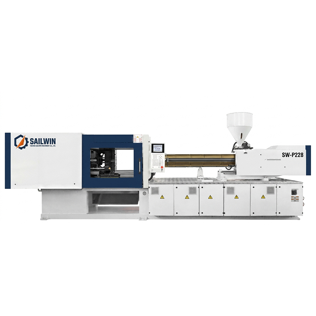
Precision Engineering & Core Components: sw p228 pet preform injection molding machine
2. Site Preparation and Utility Requirements
The table below lists the site items that should be verified before the machine arrives. The requirement column states what to prepare; the verification column states what evidence to hold, because a commitment from a contractor is not the same as a measurement. Exact figures for floor loading, power rating and water flow depend on the specific model in the SW-P range and should be taken from the machine requirement sheet for that model.
| Site item | What to prepare | Evidence to hold before arrival |
|---|---|---|
| Floor and foundation | A level, load-bearing slab sized for the machine’s mass plus the mould, with enough clearance for maintenance access on all sides | Floor flatness survey and a foundation drawing checked against the machine requirement sheet |
| Machine levelling | Levelling pads or shims at the designed support points, adjusted with a precision level before grouting or anchoring | A levelling record showing measurements at each support point, signed at handover |
| Electrical supply and earthing | A dedicated supply rated for the machine’s demand, correct conductor sizing, protection coordinated with the machine, and a clean earth | Measured voltage and phase balance at the machine terminals under load, and an earth resistance reading |
| Compressed air | A supply capable of holding the plant working pressure of roughly 8–10 bar at the machine inlet with all machine actuators and the robot moving together | Pressure logged at the machine inlet during a full machine cycle, plus air quality and dryness results |
| Chilled water | A circuit able to deliver the required flow at a supply temperature held in the 8–12 °C band, with filtration and flow indication per circuit | Flow and supply and return temperature recorded for each mould and core circuit at operating conditions |
| Resin drying and conveying | Dryer capacity matched to the machine’s throughput, with dew point measurement and a conveying route that avoids regrind segregation | Dryer performance verified against the resin supplier’s specification, and the drying procedure written down for the operators |
| Robot and take-out interface | A take-out robot matched to the platen and the tool, connected through the EUROMAP 67 interface on the machine | Interface signal test completed and robot cycle timed against the machine cycle before the production mould is installed |
| Access, lifting and spares | A route for the machine and the mould, lifting equipment rated for the heaviest component, and a defined location for the initial spare parts | Lift plan agreed in advance, and the spares list checked off against the packing list on arrival |
Two rows cause most installation delays, and neither is expensive to fix if it is caught early. Compressed air looks adequate on paper and is marginal in practice, because the peak demand occurs when the robot, the mould movements and the ejector all actuate within the same fraction of a second; sizing on average consumption rather than peak demand is the standard mistake. Chilled water is the other: a circuit sized for a smaller machine delivers the right temperature at the wrong flow, so the machine holds temperature poorly under load while appearing correct at idle.
3. Foundation, Levelling and Alignment Before the Mould Goes In
Levelling is the step most often compressed because its benefit is invisible on the day it is done. Set the machine on its designed support points, adjust each point with a precision level until the frame is level in both axes, confirm every support point is carrying load, and anchor or grout only after the level is confirmed. Re-check after the first week of operation, which catches settling that would otherwise become permanent misalignment.
Platen parallelism and tie bar alignment belong to the same exercise. A machine that is level but has non-parallel platens clamps the mould unevenly, and unequal clamping force across a multi-cavity preform tool is a direct route to uneven filling, cavity-to-cavity weight variation and accelerated wear on the mould’s leader pins. Check it with the tool out, on a clean platen face, and record the result.
Grouting or anchoring comes last, and whether to anchor at all depends on the machine size and the foundation design. What matters is that the final state is documented: a signed levelling record showing the measurement at each support point establishes that the machine was correct when installed and that any later change in level happened in service.
The cheapest mould protection you will ever buy is a levelling record made before the mould was installed. Nobody can argue with a number taken on a clean platen.
Send Your Machine Model and Site Data for an Installation Readiness Review
Share the model, foundation drawing and utility readings — our engineers return a gap list, the acceptance test schedule and the documents to collect at handover.
4. Safety Circuits, Robot Interface and the Acceptance Tests to Run
Safety circuits should be proven with the machine empty, before any tool is installed. A defeated guard interlock, a light curtain that does not stop the closing stroke, or an emergency stop that does not remove energy from the correct circuits are all faults far cheaper to find with nothing in the platens. Test every guard, every interlock, the safety gate, the emergency stop at each station and the hydraulic or servo isolation, and sign the results. The machine carries CE marking to the applicable machinery safety requirements, but factory conformity does not verify the wiring and reinstatement work done on site.
The robot interface belongs in the same pre-mould phase. The EUROMAP 67 interface on the SW-P machines is the standard connection between the machine and a take-out robot, and it should be tested through a complete cycle sequence before the production tool is installed: every signal both ways, confirmation that the mould area is clear before clamping is permitted, timing against the machine cycle so the sequence does not stretch it, and the behaviour when the robot faults mid-cycle. A robot integrated after the tool goes in is a common cause of a poor first week.
Then run the acceptance tests in a defined order, with a defined pass criterion for each, and record the results in one document. A practical sequence is to start with functions that need no material at all, then move to material and a simple tool, then to the production tool. The test list below is a workable structure for a preform installation; the specific values come from the machine and mould requirement sheets rather than from a generic table.
- Utility verification. Power under load, air pressure at the machine inlet during a full cycle, chilled water flow and temperature per circuit against the machine requirement sheet.
- Dry cycle and safety function test. Full sequence without material, with each guard, interlock and emergency stop proven and recorded.
- Temperature control verification. Barrel and hot runner zones brought to setpoint and held, with the PID stability confirmed against the machine’s stated control of about ±1 °C and the deviation trend read from the parameter log.
- Short-shot and cushion check. Shot size established, cushion position and repeatability verified, screw recovery time measured.
- Capability run with the production tool. Continuous running at target rate with preform weight, dimensions and reject count recorded per cavity, and the mould change procedure walked through with the operators.
- Handover documents. Parameter sheet per mould, utility readings signed against the requirement sheet, safety test record, levelling record, spare parts list, maintenance schedule and warranty registration.
The parameter log deserves particular attention at handover. Because the machine records 40+ parameters continuously, the first week of production documents how the process behaves from a cold start through the first temperature stabilisation, into steady state and across the first weekend shutdown. Training operators to export that history and send it with a question is far more productive than describing a symptom by telephone, and it is why Sailwin supports machines on a 7×24 remote basis with common wear parts shipping within 48 hours. The factory acceptance test proves the machine under load at the factory; the on-site record proves it in your plant, which is why installation and commissioning typically take 3 to 7 days when the site is ready first.
5. Case Study: A First Month of Weight Variation Traced Back to the Floor
A preform producer installed a new machine on an existing slab and put the production tool in as soon as it arrived, to meet a delivery commitment. From the first week, weight varied between cavities more than it had on the older machine next to it, and the difference persisted after the hot runner was checked twice.
- Production tool installed before levelling was verified, to protect a delivery date
- Persistent cavity-to-cavity weight variation that did not respond to hot runner temperature adjustment
- Chilled water circuits that delivered the correct temperature but insufficient flow under load, so mould temperature was unstable in production
- Levelling re-measured at every support point and corrected, then re-checked after the first week of thermal cycling
- Platen parallelism and tie bar alignment checked with the tool removed and the results recorded
- Chilled water flow measured per circuit at operating conditions and the circuits rebalanced, with supply temperature held in the 8–12 °C band
- Compressed air logged at the machine inlet through a full cycle including robot movement to confirm the supply held under peak demand
- The variation was a site problem, not a machine or hot runner problem, which is why two hot runner inspections had found nothing
- A levelling and parallelism record now exists for the machine, so any future change can be compared against a documented baseline
- Utility verification became a step in the next installation’s schedule rather than something discovered during the first production month
Scenario based on a Sailwin customer project; site-specific figures available on request during engineering review.
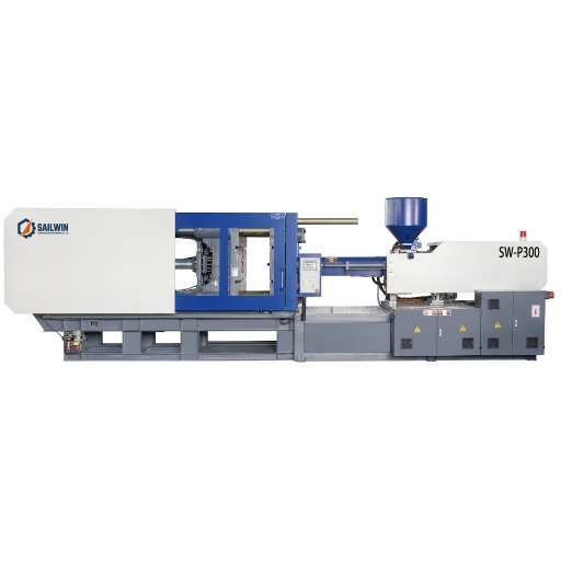
Industrial Machinery Assembly & Workshop: sw p300 pet preform injection molding machine
Frequently Asked Questions
Prepare the Site Before the Machine, and the Mould Trial Proves Something
Send your bottle drawing, container sample or target output. Our engineering team replies with a machine recommendation, mould assessment and factory-direct quotation within 24 hours.
Related Reading:
• PET Injection Molding Machines: SW-P Series from 170 to 5500 kN
• Choosing a Preform Injection Molding Machine
• Injection Molding Machine Energy Consumption
• PET Resin Drying for Injection Molding
• Robot Take-Out and the EUROMAP Interface
• PET Screw and Barrel Design for Injection Molding



