
A preform mould trial is usually scheduled as a formality at the end of a project: the machine is installed, the mould is bolted in, a few parts come out, everyone drinks coffee and signs. The problem with that approach is that the trial is the only moment when you have the tool, the machine, the resin and the customer’s technical team in the same room. If it produces opinions instead of measurements, the project leaves that room with no baseline.
The cost of a weak trial is paid for months. Without a documented process window you cannot tell whether a weight drift next quarter is the screw, the hot runner, the cooling circuit or the resin lot. Without short-shot and pressure-study data you have no defensible answer when a bottle producer complains about wall distribution. And when a new mould is added to the same machine two years later, the team re-derives everything from scratch because nothing was written down.
Sailwin has built PET preform injection machines and complete bottle production equipment for 15+ years, with 500+ machines delivered to 60+ countries, manufacturing under ISO 9001:2015 with CE marking and supporting installations with a 2-year machine warranty. The SW-P range covers 14 models from 170 to 5,500 kN, runs valve-gate hot runners up to 64 cavities, uses dedicated PET screws with far-infrared nano heater bands and offers the EUROMAP 67 robot interface. This guide sets out a trial sequence that produces evidence a plant can reuse, from dry cycle to capability sign-off.
Key Takeaways
- A trial without recorded numbers is not a trial. Weight, dimensions, cycle time, cushion position, clamp tonnage and the process window belong on a signed sheet before the mould leaves the machine.
- Sequence matters more than parameters. Dry cycle, short shots, pressure study and cooling sweep must run in that order; skipping the fill study means every later number is built on an unproven gate and balance.
- The capability run is the acceptance test. A stable run of consecutive shots at the upper and lower process limits proves the window is real, not a lucky operating point.
Running a Preform Mould Trial Next Quarter?
Send your preform drawing, resin grade and cavity count — Sailwin engineers return a machine and tooling recommendation plus a factory-direct quotation within 24 hours.
1. Define Acceptance Criteria Before the First Shot
The single most useful hour of a preform mould trial happens before the heater bands are switched on. Write down what “acceptable” means, in numbers, and get both sides to agree it in writing. Everything later becomes far simpler: each measurement either lands inside the agreed band or it does not.
A workable acceptance list covers five families of requirement. Dimensional: neck finish diameter and thread profile, body diameter, overall length, wall thickness at defined heights. Mass: preform weight with a tolerance band wide enough to be achievable across cavities, tight enough to protect the blow process downstream. Optical: gate quality, visible sink, flow lines, colour streaks. Performance: acetaldehyde level where the application demands it, top-load capability of the blown bottle, stress-crack behaviour after the intended filler. Production: cycle time, cavity-to-cavity variation and scrap rate during the run.
Two details are routinely missed. First, specify where a measurement is taken — a preform wall thickness is meaningless without a defined height and clock position. Second, agree the sample size and who measures: the plant’s own measuring routine, not the toolmaker’s, is the one that will be repeated in production.
Tolerance bands for preforms are not universal, because a 12 g water preform and a 110 g wide-mouth jar preform tolerate very different absolute deviations. What must be fixed in advance is the relationship: weight tolerance should be set as a fraction of nominal mass, and wall thickness as an absolute range at named heights. Typical industry practice for carbonated beverage preforms is to hold weight within roughly ±0.5% to ±1% of nominal and neck finish inside the drawing dimensions without exception, because the neck is the one feature the blow process and the capper both depend on. Treat those as orientation values and let the application decide.
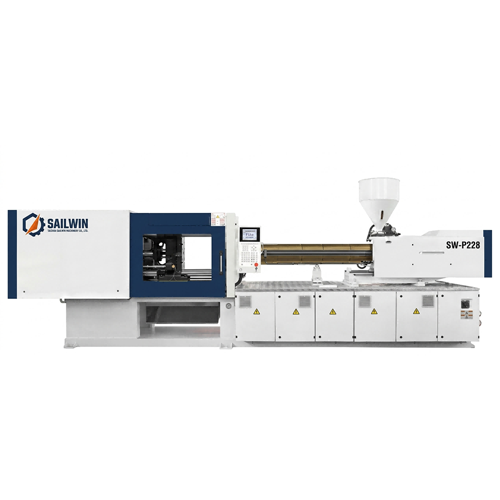
Precision Engineering & Core Components: sw p228 pet preform injection molding machine
2. Stage One: Dry Cycle and Utility Verification
Start with the machine, not the tool. A dry cycle at production speed with the mould open proves that the clamp, ejector, robot take-out sequence and safety interlocks behave before any plastic is involved. It is far cheaper to find a slow ejector or a mis-set interlock without a hot mould in the way.
Record dry-cycle time, clamp tonnage build-up, ejector stroke and the position where the take-out robot enters. On a machine with the EUROMAP 67 interface the robot handshake timing is part of this check: the moulding machine signals, the robot confirms, the cycle advances. Any hesitation here shows up later as a cycle-time problem that looks like a mould problem.
Verify utilities at the same time. Cooling water inlet temperature and flow, mould temperature controller setpoints for the cavity and the neck ring, compressed air for the robot and the valve-gate controllers, and the dry-air supply if the resin has been dried in a dehumidifying dryer. Chilled water in the 8-12 °C range is standard for mould cooling circuits, and it is worth recording the actual return temperature rather than the setpoint — the difference is your first honest number about how much heat the mould is removing.
If the machine has a PID temperature controller holding melt temperature to ±1 °C, confirm it against a purge shot or a needle probe rather than trusting the display alone. A stable melt temperature is the precondition for a repeatable fill study, and a drifting one will make the next three stages unreadable.
3. Stage Two: Short Shots and the Fill Balance Study
The fill study is the diagnostic core of the whole trial. Reduce the shot size in steps so the mouldings are progressively incomplete, and the filling pattern of the manifold, the runners and the individual cavities becomes visible. You end up with a series of parts that show exactly which cavities fill first, which fill last and how the flow front advances.
With a multi-cavity valve-gate hot runner this study is done with individual gate opening times as the variable. Start with all gates open simultaneously, learn the natural imbalance, then trim gate timing to bring the late cavities forward. On a 48 or 64 cavity layout the imbalance is usually not a defect — it is a consequence of the manifold’s natural flow-path length differences. The trial exists to measure how much trimming is needed and whether the result stays stable.
Two numbers matter at the end of this stage. The fill time spread across cavities, which tells you how much gate adjustment has to live permanently in the recipe, and the pressure at transfer for the slowest cavity, which sets your lower limit for injection pressure. If the spread is large enough that the slowest cavity needs a markedly different gate time, that is a tooling conversation to have now rather than after acceptance.
Judge the short shots on more than length. Look for hesitation marks, jetting near the gate, weld line position in relation to the neck ring, and whether the last point to fill sits where the tool design intended. A preform that fills evenly but has a visible hesitation line three millimetres below the neck will fail inspection even though its dimensions pass.
4. Stage Three: Pressure Study, Hold and Gate Freeze
With the fill pattern understood, move to the pressure study. Hold pressure is swept in steps while everything else is held constant, and each step’s parts are weighed and measured. The shape of that curve tells you where the cavity is being packed completely, where packing adds nothing, and where excess pressure starts pushing material back through the gate or building stress into the part.
Plot weight against hold pressure and you will normally see a steep rise, then a knee, then a flat region. The operating point belongs on the flat region, slightly above the knee — that is where a small variation in pressure produces a small variation in weight instead of a large one. Working at the knee means production lives one process fluctuation away from a weight excursion.
Gate freeze follows from the same data. If the gate is not frozen before hold pressure is released, material travels back out of the cavity and the part decompresses; the symptom is weight scatter between cavities and a sunken gate area. The gate seal point is best found by holding pressure for progressively shorter times at a fixed hold value and watching where weight begins to fall away. The usable hold time is comfortably beyond that point, not exactly on it.
Record four values from this stage: the cushion position that stays repeatable, the injection pressure at transfer, the hold pressure that sits on the plateau and the hold time beyond gate seal. Those four numbers, together with the fill time spread from stage two, are the skeleton of the production recipe.
| Trial stage | Question it answers | Evidence to capture | Pass condition |
|---|---|---|---|
| Dry cycle | Do machine, ejector, robot and interlocks work at production speed? | Cycle time, clamp tonnage, ejector stroke, robot handshake timing | Production cycle achievable with no fault and no interlock defeat |
| Utility check | Are cooling, air, temperature control and drying inside their design ranges? | Flow and return temperatures, controller setpoints, purge shot melt temperature | Melt temperature stable at the ±1 °C controller capability |
| Short shots | How does the melt fill the manifold and each cavity? | Progressive short-shot set, gate timing trim, fill time spread, pressure at transfer | All cavities fill with no hesitation, jetting or weld line in a critical zone |
| Pressure study | Where does packing stop adding mass and start adding stress? | Weight versus hold pressure curve, cushion repeatability | Operating point on the plateau, clearly above the knee |
| Cooling sweep | What is the shortest cooling time that holds dimensions? | Dimensional and optical results across stepped cooling times | Dimensions in tolerance with measurable margin, no post-mould shrinkage drift |
| Capability run | Does the process hold at the edges of the window? | Consecutive-shot data at nominal, upper and lower limits | Acceptance criteria met at all three points, signed by both parties |
5. Stage Four: Cooling Time and Dimensional Stability
Cooling is where cycle time is won or lost, and where most preform dimension complaints originate. Hold everything else at the values you have just established and step cooling time down. At each step, measure dimensions immediately after ejection and again after a defined settling period; a preform that measures in tolerance hot and out of tolerance two hours later was under-cooled, and the mould was never going to forgive it.
Watch the neck ring circuit specifically. The neck finish is the most dimensionally critical feature on the part and the one the blow line grips; if the neck ring is running warmer than the cavity, neck ovality will appear as a downstream problem in the blowing machine even though the preform passes a single-point gauge check.
Then look at the acetaldehyde side of the equation. Longer residence at high melt temperature and slower cooling both push acetaldehyde up, which is why cooling optimisation and drying discipline are not separate subjects from taste performance. If the application is sensitive — still water in warm markets, or any product stored for months — build an acetaldehyde check into the acceptance list rather than discovering the issue after the first market complaint.
The output of a good preform mould trial is not a running machine. It is a written process window — with a nominal recipe, a proven upper and lower limit, and the name of the person who measured each number.
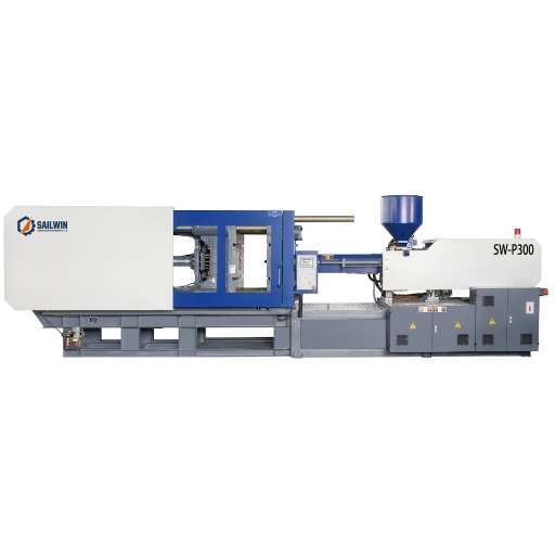
Industrial Machinery Assembly & Workshop: sw p300 pet preform injection molding machine
6. Case Study: A Beverage Plant Adding a 48-Cavity Mould
A beverage plant in South-East Asia was adding a new preform tool to an existing machine. The mould had been trialled at the toolmaker, the parts looked right, and the plant expected a one-day run-in before going straight into production.
- Mould proven at the toolmaker’s site, but no process window transferred with it
- Weight spread across the 48 cavities measured informally, with no recorded per-cavity data
- Cooling time set from a similar tool rather than from measurement on this machine
- Neck ovality complaints inherited from the previous tool and assumed to be a resin issue
- Dry cycle first to fix the robot handshake and confirm cycle time before any melt was introduced
- Progressive short-shot set to map fill balance, then gate timing trimmed cavity by cavity
- Hold pressure swept in steps and plotted against weight to place the operating point on the plateau
- Neck ring circuit separated from the cavity circuit on the temperature controller and adjusted independently
- Signed capability run at nominal, upper and lower limits, with every cavity measured
- Neck ovality traced to mould temperature control, not to the resin, and corrected before production start
- Documented recipe sheet left on the machine, so the same sequence is reused for the next tool
- Weight drift later diagnosed from the trial data instead of by re-trialling the whole mould
The lesson from that project is not about 48 cavities. It is that the mould trial is the only opportunity to convert the toolmaker’s claim into the plant’s own numbers, and that the sequence — dry cycle, fill balance, pressure, cooling — is what makes each number interpretable.
Frequently Asked Questions
Turn a Mould Trial Into a Signed Process Window
Send your bottle drawing, container sample or target output. Our engineering team replies with a machine recommendation, mould assessment and factory-direct quotation within 24 hours.
Related Reading:
• PET Preform Injection Molding Machines — SW-P Series, 170 to 5,500 kN
• Commissioning a Preform Injection Machine On Site
• How Cooling Time Is Calculated for PET Preforms
• Setting Preform Weight Tolerance and Running SPC
• Mould Steel Grades and Their Effect on Preform Quality
• Inside a 64-Cavity Valve-Gate Hot Runner Tool



