
In modern hollow plastic packaging, packaging engineers often describe the primary blow molder as the “heart” of the packaging plant. However, an industrial blow molder is completely incapable of functioning without an integrated, synchronized network of plant utilities. A high-speed 6-cavity linear stretch blow molder rated at 9,000 bottles per hour will instantly drop to zero output if the 35-bar high-pressure compressor drops 3 bar below minimum blowing threshold, if moisture from a faulty air dryer contaminates pneumatic valves, or if an undersized water chiller permits mold cavity temperatures to rise above 18°C. In commercial container packaging, over 65% of chronic cycle time penalties, container haze defects, and premature valve failures originate not within the blow molder itself, but within neglected, incorrectly sized auxiliary equipment.
Selecting and sizing the correct blow molding machine auxiliary equipment is the single most critical engineering task in turnkey packaging plant design. This comprehensive technical guide details the pneumatic and thermodynamic engineering calculations required to size 30-to-40-bar high-pressure compressors, low-pressure mechanical drive compressors, closed-loop industrial mold chillers, refrigerated air dryers, and automatic preform loaders. It establishes the quantitative relationship between mold cooling water temperature and cycle speed, contrasts multi-stage piston boosters with rotary screw compressor architectures, and provides a turnkey auxiliary budget and specification checklist to ensure your packaging line operates at peak overall equipment effectiveness (OEE).
| Auxiliary Sub-System | Primary Engineering Function | Operating Pressure / Spec | Sizing Metric / Formula | Consequence of Undersizing |
| High-Pressure Air Compressor | Supplies pre-blow and final high-pressure container inflation air. | 30 – 40 Bar (435 – 580 PSI) | BPH × Container Vol (L) × Blow Bar × 1.3 Safety factor ÷ 60,000 | Blown containers exhibit rounded, soft base petaloids, insufficient burst strength, and delayed cycle times. |
| Low-Pressure Air Compressor | Drives pneumatic mold clamping cylinders, preform infeed valves, and discharge arms. | 8 – 10 Bar (116 – 145 PSI) | Total pneumatic cylinder CFM consumption + 25% overhead | Chattering mold platen movement, erratic preform loading, and safety door interlock pressure faults. |
| Industrial Mold Water Chiller | Extracts thermal energy from mold cavity tooling and neck protection shields. | 10°C – 14°C (Supply Temp); ≥ 3.5 Bar Pressure | Hourly resin throughput (kg/hr) × Specific heat × ΔT ÷ 3,600 | Extended mold cooling dwell (+1.5 to 3.0s), container shrinkage, sidewall denting, and deformed bottle necks. |
| Refrigerated Air Dryer & Filters | Eliminates moisture, oil vapor, and particulate dust from blowing air stream. | Pressure Dew Point: +2°C – +5°C; Residual Oil <0.01 mg/m³ | ISO 8573-1 Class 1.4.1 Filtration Rating | Internal water droplets cause bottle bottom pinholes, foggy haze, and corroded blowing solenoid valves. |
| Auto-Loader & Hopper Elevator | Automatically transfers bulk preforms from ground bin to orientation unscrambler. | Stainless Steel Infeed Bin; Level Sensor Control | Conveyor throughput capacity ≥ 120% of rated machine BPH | Machine preform starvation, frequent line micro-stops, and excessive manual labor requirements. |
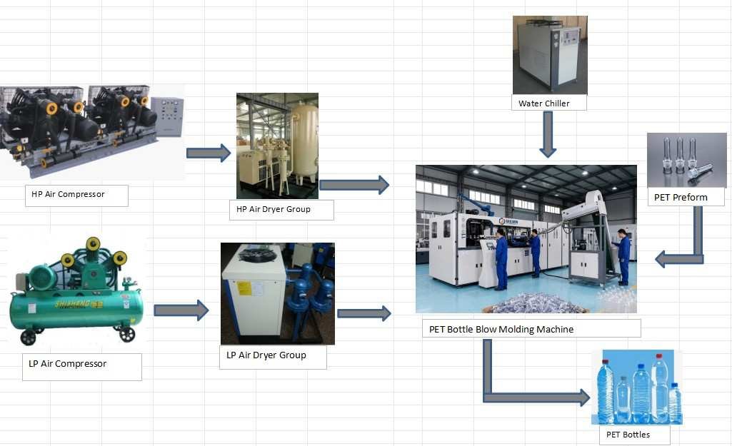
Why Auxiliary Equipment Is the Hidden Packaging Bottleneck
When factory managers evaluate packaging plant performance, auxiliary utilities are often treated as secondary commodities. This operational perspective causes major recurring productivity losses:
- Thermal Cooling Time Penalties: Plastic containers do not achieve dimensional stability until polymer temperature drops below glass transition ($T_g$). If an undersized chiller circulates 22°C water instead of 11°C chilled water, the mold must remain clamped an extra 1.8 seconds per cycle. On a 4-cavity line, that thermal penalty reduces daily output by over 14,000 bottles.
- Pressure Curve Ramp Starvation: High-speed PET stretch blow molding requires the cavity to reach 30 to 35 bar within 0.08 to 0.12 seconds after pre-blow. If the high-pressure compressor displacement or air receiver storage volume is inadequate, pressure ramps sluggishly, resulting in thick container base corners and structural collapse under top-load testing.
- Moisture & Oil Contamination: Standard ambient air compressed to 35 bar concentrates ambient water vapor by 35 times. Without refrigerated air dryers and multi-stage coalescing filters, aerosolized moisture injects directly into preforms during inflation, creating localized steam pockets, hazy surface streaks, and water droplet corrosion that destroys $15,000 high-pressure valve manifolds.
High-Pressure Air Compressor System: Sizing 30–40 Bar for PET Blowing
In PET stretch blow molding machinery lines, compressed air is consumed as a primary raw utility:
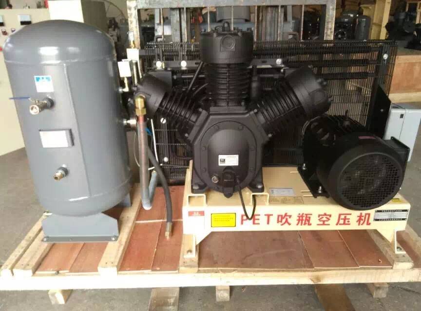
1. High-Pressure Air Volume Calculation Model
To determine the required compressor displacement ($Q_{\text{HP}}$ in $\text{m}^3/\text{min}$ at standard atmospheric pressure), engineers apply the container volumetric consumption formula:
- $V_{\text{bottle}}$ = Container nominal volume in Liters (e.g., 0.5L, 1.5L, or 5.0L).
- $P_{\text{blow}}$ = Final high-pressure blowing pressure in bar absolute (typically 30 to 35 bar).
- $\text{BPH}$ = Rated production speed in bottles per hour.
- $C_{\text{loss}}$ = Air exhaustion and dead volume factor (typically 1.15 to 1.25 for mold valve manifolds).
- $C_{\text{safety}}$ = Compressor operational safety margin (1.15 to 1.20 to prevent 100% duty cycle overload).
Engineering Sizing Example: Sizing for an automatic blow molding machine producing 4,000 BPH of 500ml water bottles at 32 bar blowing pressure:
$Q_{\text{HP}} = [ (0.5 \times 32 \times 4,000) \div 60,000 ] \times 1.20 \times 1.15 \approx \mathbf{1.47\text{ m}^3/\text{min}}$ (FAD @ 35 bar). A minimum 22 kW to 30 kW high-pressure compressor station is required.
Planning a New Packaging Plant and Need Turnkey Utility Sizing?
Avoid costly utility mismatches. Send your target container volumes, resin types, and hourly output goals to Sailwin’s plant engineering division. We generate a complete synchronized utility flow diagram and itemized auxiliary equipment budget within 24 hours.
Rotary Screw Booster vs Multi-Stage Reciprocating Piston
Plant engineers choose between two primary high-pressure compression architectures:
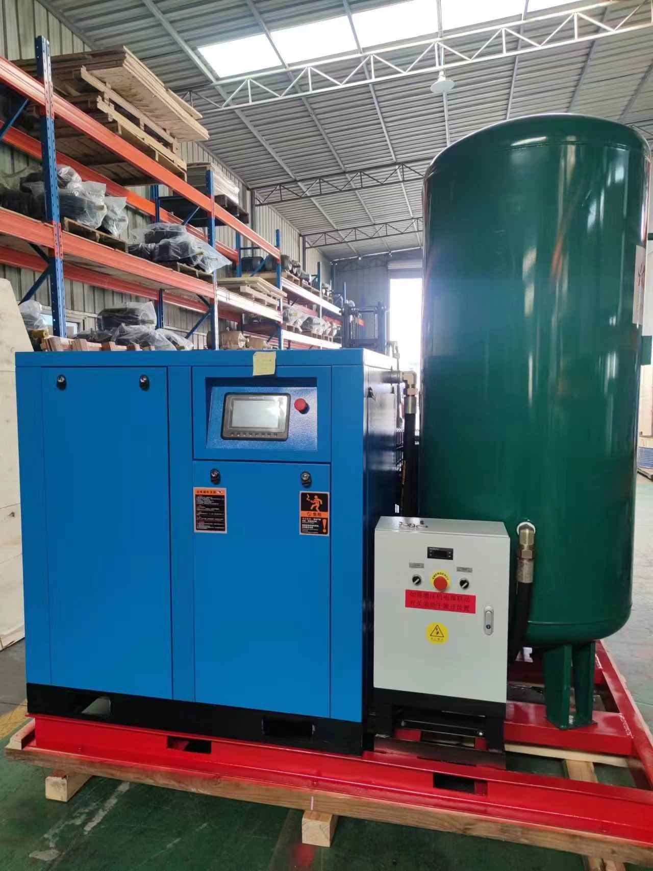
| Comparison Dimension | Multi-Stage Reciprocating Piston | Screw Compressor + High-Pressure Booster |
| Capital Investment | Economical initial purchase cost; widely accessible. | Moderate capital investment; higher initial configuration cost. |
| Duty Cycle & Reliability | Recommended 60%–75% duty cycle; needs rest intervals. | 100% Continuous Duty Cycle; designed for 24/7 non-stop bottling. |
| Noise & Vibration Level | High mechanical vibration and pulsing noise (78 – 85 dB). | Smooth rotary motion with acoustic enclosure (< 68 – 72 dB). |
| Oil Carryover to Bottles | Requires rigorous multi-stage oil filtration maintenance. | Integrated oil separation; ultra-clean air delivered to molds. |
| Recommended Plant Scale | 1,000 – 4,000 BPH lines or intermittent shift packaging. | 6,000 – 24,000 BPH continuous high-speed lines. |
Industrial Water Chiller: Sizing Mold Cooling for Maximum Speed
In both PET stretch blow molding and extrusion blow molding (EBM) lines, container cooling dictates production output:
1. Chiller Cooling Capacity Calculation Formula
- $M_{\text{plastic}}$ = Total plastic throughput per hour in kilograms (BPH × container weight in grams ÷ 1,000).
- $c_{\text{resin}}$ = Specific heat capacity of the polymer ($\text{PET} \approx 1.30\text{ kJ/kg}\cdot\text{K}$; $\text{HDPE} \approx 2.30\text{ kJ/kg}\cdot\text{K}$).
- $T_{\text{melt}} – T_{\text{eject}}$ = Temperature drop from blowing temperature to safe ejection temperature ($\Delta T \approx 70\text{K}$ to $90\text{K}$).
- $1.25$ = Safety factor accounting for mold platen ambient heat gain and pumping friction.
2. The Golden Rules of Blow Mold Water Chilling
- Maintain Turbulent Flow ($Re > 4,000$): High water velocity through mold cooling channels transfers heat 3.5 times faster than sluggish laminar flow. Ensure supply pressure exceeds 3.5 bar across all mold manifolds.
- Dual-Circuit Cooling for Hot-Fill or Deep Base Petaloids: Large containers and hot-fill bottles benefit from independent dual-temperature chillers: circulating 10°C chilled water through the mold base push-up to freeze thick gate plastic, and 16°C water through sidewalls to prevent ambient mold sweating in humid summer climates.
Air Purification & Moisture Control: ISO 8573-1 Standard
Compressed air entering food and beverage packaging molds must meet stringent purity standards:
- Refrigerated Air Dryer: Cools compressed air down to +2°C to +5°C pressure dew point, condensing vaporized water into bulk liquid for automated expulsion.
- 3-Stage Coalescing Pre-Filtration: Multi-stage filter cartridges capture solid particulates down to 0.01 micron and reduce residual hydrocarbon oil aerosol content to below 0.01 mg/m³.
- Air Storage Receiver Tanks: Certified vertical pressure vessels installed immediately downstream of compressors buffer pressure fluctuations and allow gravity condensate drop-out before air enters delicate machine valve manifolds.
Turnkey Auxiliary Line Sizing Benchmark: 4-Cavity High-Speed Production
(Representative industrial packaging benchmark based on a standard 4-cavity linear PET bottling line)
Standard Machine Specifications: Automatic 4-cavity linear stretch blow molder operating at 6,000 BPH of 500ml water bottles (13.5g PET preform weight; 32 bar blowing pressure):
| Synchronized Utility Unit | Engineered Capacity Specification | Operational Purpose |
| High-Pressure Air Compressor | 2.4 m³/min @ 35 Bar (30 kW Screw/Piston) | Provides sustained 32-bar container stretch and mold cavity replication. |
| Low-Pressure Air Compressor | 1.2 m³/min @ 8 Bar (7.5 kW Screw) | Drives preform infeed cylinders, mold toggle clamping, and safety doors. |
| High-Pressure Air Receiver Tank | 1,000 Liters @ 40 Bar (Vertical Vessel) | Absorbs multi-cavity pressure draw-down; buffers line pressure drops. |
| Refrigerated Air Dryer & Filters | 2.6 m³/min @ 40 Bar (ISO 8573-1 Class 1.4.1) | Dew point ≤ 3°C; ensures 100% moisture-free container blowing air. |
| Industrial Water Chiller | 10 HP (Approx. 28 kW Cooling Capacity) | Circulates 11°C chilled water through molds to lock container geometry. |
| Automatic Preform Elevator | Stainless Steel Hopper + Flighted Belt | Feeds 7,200 preforms/hour automatically without manual bin dumping. |
Benchmarked Engineering Outcomes: By fully synchronizing auxiliary capacities to machine demand, packaging facilities eliminate micro-stops, maintain constant bottle burst pressures exceeding 14 bar, and protect primary blow molding equipment investments under ISO 9001 certified manufacturing quality standards.
Ready to Engineer a Balanced, High-Efficiency Packaging Line?
Sailwin provides complete turnkey packaging line packages: blow molders, matching screw/piston compressors, certified pressure vessels, precision chillers, and air treatment systems perfectly configured for your bottles.
Frequently Asked Questions: Auxiliary Equipment for Blow Molding Lines
Why do PET blow molding machines require two different air compressors?
Linear stretch blow molding utilizes two distinct pressure stages: low-pressure air (8–10 bar) to drive pneumatic toggle clamping cylinders and mechanical robot transfer grippers, and high-pressure air (30–40 bar) to rapidly expand the heated preform into the mold cavity. Separating these systems prevents high-pressure draw-down from disrupting mechanical indexing mechanisms.
What is the difference between air-cooled and water-cooled chillers?
Air-cooled chillers utilize integrated radiator fans to dissipate heat into ambient factory air; they require zero external cooling tower water and install quickly. Water-cooled chillers transfer heat to an external evaporative cooling tower; they offer 15% to 25% higher electrical efficiency in extreme ambient summer climates (over 40°C), making them ideal for heavy tropical manufacturing facilities.
What size air storage tank is required for a 6,000 BPH blow molder?
For a 6,000 BPH line consuming ~2.4 m³/min of 30-bar air, install a certified vertical receiver tank with a minimum volume of 1,000 Liters (1.0 m³) rated for 40 bar working pressure. The receiver buffers the instantaneous multi-cavity pressure drop during high-pressure blowing triggers.
What causes water droplet defects inside blown PET bottles?
Moisture inside finished bottles indicates refrigerated air dryer failure. If air dryer refrigerant leaks, or if automatic condensate drain valves clog, liquid water bypasses filtration and injects into hot preforms, instantly boiling into steam pockets that create internal cloudy hazing and blowouts.
How does an automatic preform loader improve packaging plant ROI?
An automatic preform elevator equipped with photoelectric sensors eliminates the physical labor of workers dumping heavy 20kg preform cartons into elevated bins every 15 minutes. It prevents operator fatigue, eliminates preform starvation shutdowns, and ensures clean, scratch-free preform delivery into orientation rollers.
Can I use an oil-lubricated compressor for food-contact bottle packaging?
Yes, provided the compression station incorporates multi-stage oil coalescing filters, activated carbon tower scrubbers, and refrigerated dryers conforming to ISO 8573-1 Class 1.4.1 or Class 1.2.1. Alternatively, 100% oil-free reciprocating compressors or water-injected screw boosters eliminate all risk of hydrocarbon oil aerosol carryover into drinking water containers.
How often should air compressor and chiller filters be serviced?
Inspect pre-filters and drain condensate bowls daily. Replace compressed air coalescing filter cartridges every 6 to 12 months (or whenever differential pressure exceeds 0.35 bar). Flush chiller water strainer baskets monthly to prevent calcium scale from choking mold flow rates.
Does Sailwin supply complete turnkey auxiliary equipment with blow molding machines?
Yes. Sailwin delivers synchronized, pre-tested turnkey packages comprising matched high-pressure compressors, vertical air receiver tanks, refrigerated dryers, modular mold chillers, and stainless steel auto-loaders engineered to connect seamlessly to our blow molding machinery.
Summary & Related Machinery Guides
Auxiliary equipment is the functional foundation that determines packaging plant output, energy cost, and container cosmetic consistency. Correctly sizing high-pressure air compressors (30–40 bar), maintaining turbulent closed-loop mold cooling (10–14°C), enforcing strict refrigerated air drying (ISO Class 1.4.1), and automating preform infeed transforms standalone machinery into a high-availability, low-waste container production line.
To further advance your packaging line engineering, review our related technical resources:
- Blow Molding Machine Engineering Knowledge Hub — Sizing and operating industrial blow molding systems.
- PET Blow Molding Machine Series Catalog — Automatic 2-cavity to 6-cavity linear stretch platforms.
- Automatic PET Blow Molding Machine Models — High-speed fully automated container production lines.
- Extrusion Blow Molding (EBM) Series — Turnkey extrusion machinery and auxiliary configurations.



