
Updated: 2026 Engineering Standard · By Sailwin Technical Team
Blow Mold Design Guide: How Cavity Materials, Cooling Channels & Pinch-Off Dictate Bottle Output
In high-speed hollow plastic manufacturing, engineering teams often spend hundreds of thousands of dollars optimizing linear stretch blow molders or heavy-duty extrusion blow molding machines, only to suffer from sluggish cycle times, chronic bottle ovalization, and high rejection rates. The fundamental bottleneck is rarely the machine clamp or servo hydraulics—it is a flawed blow mold design that treats the tooling cavity as a passive metal box rather than an active thermal heat exchanger.
In industrial bottle blow molding, 65% to 75% of your total cycle time is consumed solely by extracting heat from molten resin below its glass transition or heat deflection temperature (HDT). An unoptimized cooling passage layout or the wrong tooling alloy selection directly translates into a 3 to 6-second cycle penalty per shot. For an 8-cavity water bottling plant running 24/7, that thermal drag causes an annual output loss exceeding 4.2 million bottles, alongside massive electrical waste.
Drawing from over 15 years of factory tooling engineering and thousands of multi-cavity mold deployments across 60+ countries, this comprehensive technical blueprint deconstructs modern blow mold design. We deliver engineering calculations across cavity metallurgy (Aircraft Aluminum 7075-T6 vs. P20 Steel vs. Beryllium Copper), turbulent fluid flow dynamics (Reynolds number Re > 4,000), pinch-off relief geometries, and micro-venting standards to help plant managers achieve maximum bottle structural rigidity at the lowest cost per unit.
Key Engineering Takeaways
- Metallurgy Determines Cycle Speed: Aviation Aluminum 7075-T6 dissipates thermal energy 4.5 times faster than standard P20 tool steel (135 W/m·K vs. 29 W/m·K), enabling outputs up to 2,000 bottles per cavity/hour on high-speed PET water bottle blowing lines.
- Beryllium Copper Cuts Bottlenecks by 30%: Inserting CuBe2 / C17200 alloy along heavy pinch-offs and hollow bottle handles eliminates localized thermal hotspots in extrusion blow molding machines, preventing tail splitting and trimming total cycle time by 25%–30%.
- Venting & Pinch-Off Precision: Standardized 0.02–0.04mm parting line venting grooves combined with 0.3–0.8mm pinch-off land widths eliminate orange-peel surface defects, weld line weaknesses, and catastrophic drop-test failures.
Looking to Upgrade Your Bottle Mold Tooling or Cut Cycle Time?
Send your container drawings (STP/DWG) for free DFM mold flow simulation and factory-direct pricing.
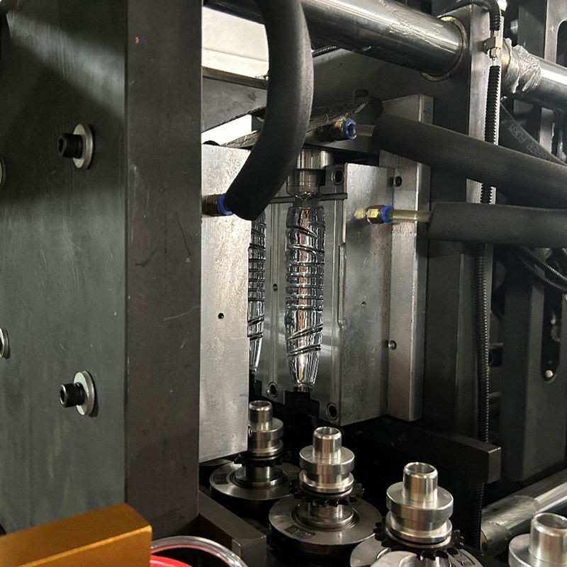
1. Tooling Metallurgy: Aluminum 7075-T6 vs. P20 Steel vs. Beryllium Copper
Metallurgy Selection Law: “Thermal conductivity dictates hourly bottle output; hardness dictates tooling depreciation cost.” In high-speed packaging, Aluminum 7075-T6 delivers 4.5× faster heat dissipation than steel, whereas Beryllium Copper inserts solve chronic pinch-off burnout in extrusion tooling.
Selecting the appropriate alloy for your cavity blocks is not a cosmetic choice—it determines your machine’s hourly output ceiling and lifetime maintenance expenditure. Tooling engineers must rigorously evaluate the trade-off between heat transfer coefficients (thermal conductivity in W/m·K) and Rockwell C surface hardness (HRC) to resist high-pressure air deformation.
| Tooling Alloy | Thermal Conductivity | Hardness | Cooling Index | Optimal Application on Sailwin Lines |
|---|---|---|---|---|
| Aviation Aluminum 7075-T6 | 130 – 150 W/m·K | 32 – 36 HRC | ★★★★☆ (Fast Quench) | PET water, edible oil, and CSD bottles. 5–8M blows lifespan. |
| P20 Pre-hardened Steel (1.2311) | 28 – 32 W/m·K | 30 – 34 HRC | ★★☆☆☆ (Standard Rate) | Heavy EBM chemical drums, Jerrycans, and abrasive PCR resins. 10M+ cycles. |
| Beryllium Copper (CuBe2 / C17200) | 105 – 130 W/m·K | 38 – 44 HRC | ★★★★★ (Hot-Spot Extraction) | Neck ring inserts, pinch-off blades, handle slides, and thick base inserts. |
Why Aluminum 7075 Dominates PET Stretch Blowing: On our automatic PET stretch blow molding machines, preforms enter the cavity reheated to 95°C–115°C. To freeze the biaxial molecular orientation and lock in container optical clarity, the metal cavity must quench the plastic below 70°C in under 1.5 to 2.2 seconds. Aluminum 7075 conducts thermal energy 4.5 times faster than standard P20 steel, allowing 18,000 BPH complete bottling installations paired with monobloc liquid filling production lines without bottle surface hazing.

2. Cooling Channel Fluid Dynamics: Conformal Circuits & Turbulent Flow
Fluid Dynamics Rule: “Laminar flow insulates; turbulent flow quenches.” Simply increasing chiller pump volume without achieving a Reynolds Number Re > 4,000 wastes pumping kilowatt-hours while leaving bottle petaloids soft and wobbly.
Drilling straight cooling holes through a mold block is no longer sufficient for modern cycle times. The internal thermal transfer rate is governed by the Reynolds Number (Re) of the circulating chilled water:
Optimal Engineering Target: Re > 4,000 (Fully Turbulent Vortex Flow)
- Laminar Flow (Re < 2,300): Water moves in smooth parallel layers. The fluid touching the hot metal quickly heats up, creating a stagnant boundary layer that acts as a thermal insulator.
- Turbulent Flow (Re > 4,000): Chilled water creates chaotic, swirling microscopic vortices that continuously wash the metal boundaries, boosting convective heat transfer coefficients by 300% to 500%.
3. Pinch-Off Geometry in EBM: Eliminating Bottle Flash & Weld Seam Failures
Pinch-Off Precision: “A knife-sharp land cuts flash but causes drop-test ruptures; an oversized land requires brutal clamping force and leaves brittle welds.” Standardizing pinch land width to 0.3–0.8mm with a 35° relief angle solves 90% of seam leaks.
In extrusion blow molding, when the mold platens clamp together, the tool steel pinch-off must accomplish two opposing tasks at the same millisecond: sever excess molten parison (tail slug and handle flash) while fusing the two polymer edges into a hermetic, impact-resistant weld seam.
- Crushing Land Width: Must be maintained strictly between 0.3mm and 0.8mm. If wider than 1.0mm, machine clamping force spikes, stressing toggle linkages without properly welding parison seams. If razor-sharp, the flash is severed before sufficient polymer molecules cross-diffuse, causing bottom leaks upon impact.
- Relief Angle (Flash Pocket): Machined at a 30° to 45° taper directly behind the land. This relief volume collects displaced molten polymer without compressing plastic against the mold back-plates, preventing mold face bowing.
- Modular Tool Steel Inserts: High-wear pinch zones are built as replaceable inserts machined from DIN 1.2379 (D2 tool steel) vacuum hardened to 56–58 HRC, allowing 15-minute quick replacements during plant changeovers.
4. Tooling Synchronization: Pairing Preform Molds with Blow Molds
A packaging container’s structural integrity starts well before the blow mold: upstream preform neck concentricity and gate crystallization directly determine bottle sidewall uniformity. When factory managers source PET preform injection molding machines and blow molders from disconnected vendors, mismatched gate dimensions and uncontrolled axial stretch ratios frequently cause erratic wall thinning and bottom blowout defects.
Sailwin Tooling Case Study: Bottled Water Producer Slashes Cycle Time by 26%
How a 6,000 BPH mineral water facility replaced generic steel blow mold cavities with Sailwin Aviation Aluminum 7075-T6 tooling, eliminating bottom rocker defects and boosting daily container output.
- Commercial water bottling plant in Southeast Asia running 500ml lightweight PET bottles.
- Old steel cavities suffered from sluggish cooling, requiring a 4.1-second blow timer.
- Over 3.8% bottle rejection due to petaloid rocker bottoms and conveyor jams.
- Engineered 6-cavity molds using Aviation Aluminum 7075-T6 with nickel plating.
- Integrated independent turbulent cooling circuits (Re > 4,200) on bottom petaloid cups.
- Calibrated micro-slotted parting line vents (0.025mm) for instant atmospheric air exhaust.
- Cooling Cycle Cut: Shaved from 4.1s to 2.9s (26.8% faster output).
- Scrap Reduction: Bottle scrap plummeted from 3.8% to under 0.2%.
- Full Payback: Total tooling investment recouped in less than 4 months.
Data source: Sailwin Customer FAT Log and Commercial Bottling Commissioning Report, 2026.
Frequently Asked Questions About Blow Mold Design
SAILWIN MACHINERY · FACTORY-DIRECT TOOLING
Ready to Optimize Your Bottle Mold Tooling & Cut Production Cycles?
Upload your 3D container CAD files (STEP / IGS / DWG) or container target specs. Our senior mold engineers will deliver a complete DFM flow simulation, cavity layout, and factory-direct quotation within 24 hours.
Explore Matched Packaging Machinery & Production Lines:
• PET Water Bottle Blowing Machine – 1,000 to 8,000 BPH linear servo stretch blow molders.
• PET Preform Injection Molding Machine – 14 models, 1,700–5,500 kN, multi-cavity hot runner systems.
• Liquid Filling Machine & Bottling Lines – 3-in-1 rotary monoblocs from 2,000 to 18,000 BPH.
• HDPE Extrusion Blow Molding Machine – Continuous & accumulator systems for 0.5L–200L containers.
• Need dedicated tooling calculation? Contact our engineering team for free 3D bottle DFM advice.



