
A pasteurization filling line is usually assembled from two projects. The thermal treatment is bought from one supplier, the filler from another, and each is specified against its own datasheet. On paper both meet their guarantees. In operation the line produces product that fails a micro test, or a filler that has to run far below its rated speed, and the two suppliers point at each other.
The cost of that split is not only disputes. Thermal treatment and filling share a deadline that nothing else on the line can absorb: product leaving the pasteuriser has a known temperature and a finite allowable hold before it must be sealed. Every minute of buffer, every metre of pipe, every stoppage of the filler consumes part of that allowance. A line that treats and fills as separate systems ends up buying the slack back in oversized buffer tanks, higher rework and slower running speeds than the equipment can actually deliver.
Sailwin has built liquid filling equipment for 15+ years, with 500+ machines delivered to 60+ countries, manufacturing under ISO 9001:2015 with CE marking and supporting installations with a 2-year machine warranty. The range includes 3-in-1 rinsing-filling-capping monoblocs, hot-fill lines for juice and tea, isobaric lines for carbonated products, 5-gallon filling systems and product-contact parts in SUS304 and SUS316L. This guide covers what changes when thermal treatment and filling are designed as one system: staging temperatures, buffer sizing, aseptic boundaries, line balancing and the commissioning sequence that proves the combination works.
Key Takeaways
- Thermal treatment and filling share one clock. The hold time available after pasteurisation — not the filler’s rated speed — sets the real capacity of the line.
- The choice of HTST or tunnel defines the filler specification. Product temperature at the filler decides whether you need hot-fill-rated valves, a counter-pressure system or an aseptic enclosure.
- Buffer volume is a design decision, not a safety net. Size the buffer from the filler’s realistic stoppage profile, then prove it with a temperature log at commissioning.
Building a Pasteurisation and Filling Project Together?
Send your product, target output and required shelf life — Sailwin engineers return a filling configuration matched to your thermal process plus a factory-direct quotation within 24 hours.
1. Design the Thermal Process and the Filler as One System
Start with the product: its pH, its solids, its sensitivity to heat, and the shelf life and storage conditions it must survive. Those four facts generate the required process — a temperature and time combination with a defined lethality — and that process in turn generates the temperature of the product arriving at the filler. Only then does it make sense to talk about filling valves, capping torque or container materials.
What makes this a systems problem is that the two halves constrain each other in both directions. The filler sets the flow rate the pasteuriser must match; the pasteuriser sets the temperature the filler must tolerate; the buffer between them sets how much of the filler’s stoppage time can be absorbed before product has to be diverted or dumped. Change any one of the three and the other two move.
The practical consequence is a design rule that is easy to state and routinely ignored: specify the filler and the thermal process from the same set of numbers, agreed in one document. Flow rate at the filler inlet, product temperature and its tolerance band, maximum allowable hold time after treatment, container format and material, closure type and the cleaning regime. When those six items are fixed together, the interface between the two systems stops being a negotiation.
It is also worth defining what “pasteurised” will be verified against. For many juice and tea products the industry works with pasteurisation units, a measure of accumulated lethality that allows different time and temperature combinations to be compared. Because the units depend on the reference temperature and the z-value assumed for the target organism, the definition should be written into the specification rather than left to the equipment supplier’s standard configuration — otherwise two suppliers can both claim compliance while meaning different things.
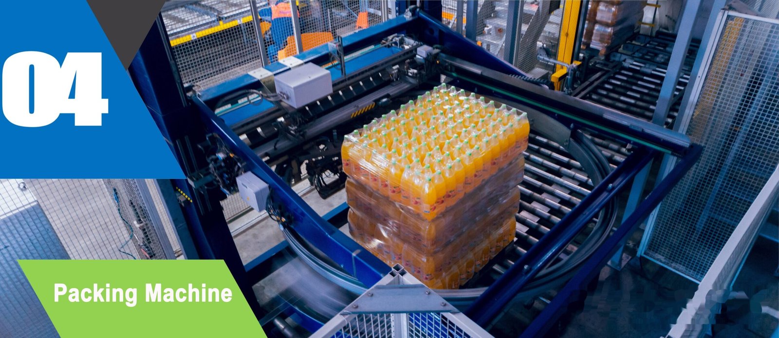
Precision Engineering & Core Components: turnkey bottling line step 04 shrink wrapping packing machine
2. Choosing Between HTST and Tunnel Pasteurisation
There are two mainstream routes, and the choice changes the filling machine more than it changes the pasteuriser.
In HTST — high-temperature short-time — the product is treated in a continuous flow before it ever reaches a container, typically in the region of 90–95 °C for 15–30 seconds for many juice and tea applications, then cooled to the temperature required at the filler. Because the product is treated as a liquid stream, the process is compact, energy recovery through regeneration is practical, and the filler receives product at a known, controlled temperature. The container is not thermally treated, which means the container and closure must be clean and the filling environment must protect the product between filling and sealing.
In tunnel pasteurisation, filled and sealed containers pass through a spray tunnel with successive temperature zones. Typical industry bands run around 60–62 °C in the pasteurisation zone with 20–30 minutes of residence, followed by controlled cooling — the exact combination is set by the product and the target organism, and the profile across the tunnel matters as much as the peak. The advantage is that the sealed package is treated, so recontamination risk after filling is much lower. The costs are a large machine, significant water and energy consumption, thermal stress on the container and closure, and a line layout that has to accommodate a long tunnel after the filler.
| Aspect | HTST (product treated before filling) | Tunnel (package treated after filling) |
|---|---|---|
| Typical industry parameters | Around 90–95 °C for 15–30 s, then cooled to fill temperature | Around 60–62 °C for 20–30 min across zones, then controlled cooling |
| What the filler must handle | Hot product at a controlled temperature; hot-fill-capable valves, product circuit and capper | Product at ambient or warm fill temperature; container must tolerate the tunnel afterwards |
| Recontamination risk | Managed by container hygiene, filling environment and closure integrity | Low after sealing; the closed package is what gets treated |
| Utilities and footprint | Compact; heat recovery by regeneration is practical | Long machine, large water and steam demand, high cooling load |
| Effect on the container | Container sees hot product; material and wall design must suit the fill temperature | Container and closure see the full thermal cycle, including cooling |
| Best fit | Clear juices and teas, high-speed lines, plants with clean-room discipline at the filler | Pulp-containing or viscous products, carbonated products, lower-speed lines with space available |
Those parameters are typical industry bands for orientation. The governing figure is always the validated process for your product, developed against the organism you are targeting and confirmed by your own micro testing — not by the values in a supplier’s brochure.
A heat treatment completes in the pasteuriser. A shelf-stable product completes at the sealer. The interface between the two — temperature, hold time, container hygiene — is where most of the risk lives, and it is nobody’s scope unless somebody writes it down.
3. Temperature Staging and Buffer Sizing
Once the process route is chosen, the next question is what happens to the product between the outlet of the treatment stage and the filling valves. That distance is where temperature is lost, where hold time is consumed and where the filler’s stoppages are either absorbed or sent back to the pasteuriser as a dump.
Specify three temperatures rather than one: the temperature leaving the treatment stage, the minimum acceptable temperature at the filling valve, and the temperature actually delivered into the container. The difference between the second and third is not academic — a hot-fill application relies on the filled product’s temperature to sanitise the container wall and the closure, so a product that cools through an uninsulated pipe run arrives too cold and the closure no longer sees the temperature the validation assumed. Insulation, trace heating and short pipe runs are all legitimate engineering answers; ignoring the loss is not.
Buffer sizing is arithmetic with a safety margin, and it should be done from data rather than instinct. Take the filler’s realistic stoppage profile — not its theoretical uptime, but the duration of the common stoppages in your plant, such as label reel changes, capper jams or conveyor blockages — and multiply by the flow rate to get the volume that must be held. Then check the resulting hold time against the allowable limit for the product. If the required buffer implies a hold time longer than the process allows, the answer is not a bigger tank; it is either a faster recovery from stoppages or a divert-and-reprocess strategy with its own validated parameters.
Where the buffer tank is heated, its temperature control deserves the same attention as the pasteuriser itself. A tank holding product just below pasteurisation temperature for an extended period is a growth opportunity for anything that survived the process, so the residence time in the buffer belongs in the validation and the tank belongs in the cleaning routine. This is one of the practical advantages of a 3-in-1 monobloc layout, where the rinsing filling capping stations share one frame and the product path between the tank outlet and the filling valve is short, visible and covered by a single cleaning procedure.
Two smaller interface items are worth agreeing in the same document. First, the cooling medium: chilled water in the 8–12 °C band is common for post-treatment cooling and for the filler’s own cooling needs, so the chiller is a shared resource and its capacity should be calculated for the combined load rather than twice, once per supplier. Second, the cleaning and sterilisation sequence between the two systems — where the CIP circuit begins and ends, which valves are shared, and who is responsible for the boundary valve.
4. What Changes at the Filling Machine
Thermal treatment upstream changes the filling machine specification in specific, listable ways. Four of them decide whether the line runs as designed.
Valve and seal material. Hot product at 85–95 °C is a different duty from ambient water. Elastomer seals, diaphragms and product hoses have to be rated for the temperature and for the cleaning chemistry, and the same applies to the filling valves themselves. On Sailwin hot-fill lines the product path is built in SUS304 or SUS316L with components selected for the fill temperature rather than for a general beverage duty — and the material certificate should be part of the handover pack.
Filling method and foam control. Hot product foams differently from cold product, and foam is a filling accuracy problem: it wets the neck, interferes with the fill level and confuses volumetric or flow-meter measurement. Laminar-flow filling valves that deliver product down the container wall rather than dropping it into the base are the standard answer, and the fill-level target should be reset for the actual product temperature rather than carried over from a cold-fill trial. For carbonated products a different route applies: the product is cooled before filling and the filler works on counter-pressure, which is why isobaric filling for carbonated drinks sits in a different process family altogether.
Capping and headspace. A hot-filled container contracts as it cools, which is why hot-fill closures and neck finishes are designed with that contraction in mind and why the headspace volume is a process parameter, not a leftover. Capping torque has to stay inside a window that holds pressure and vacuum without damaging the finish, and the capper therefore needs torque control that does not drift with temperature. Constant-magnetic-torque capping heads are used for this reason, set against a torque measurement taken on the actual filled container at the actual product temperature.
Hygiene zone and aseptic boundary. If the product is treated before filling and then cooled, the filling area becomes the last barrier against recontamination. That may mean an enclosed filling zone with filtered air and positive pressure, defined gowning and access, and a container-rinsing or decontaminating step immediately before filling. Decide the boundary early; retrofitting an enclosure around a filler that was laid out for open filling is expensive and usually compromises access.
The common thread in all four is that the filling machine should be specified from the process, not adapted to it afterwards. Sailwin hot-fill lines for juice and tea are configured around the intended fill temperature, container format and closure, then verified with a 24-hour factory acceptance test before shipment — a test that is only meaningful when the machine’s duty has been defined as part of the same project as the thermal process.
5. Line Balancing, Utilities and the Commissioning Sequence
A pasteurisation and filling line balances around one constraint at a time: whichever machine runs slowest sets the output, and whichever stage has the least buffer absorbs the disruption. Usually the thermal process is the fixed-cost element, so the filler should be specified with enough margin to run slightly faster than the treatment stage can feed it — not the other way round. Running a filler at its rated speed while starving it from upstream is the most common way to buy capacity you never actually produce.
Utilities are the second balancing act and they are routinely underestimated because each supplier calculates only its own consumption. Steam or hot water for the treatment stage, chilled water at 8–12 °C for cooling and for the filler, compressed air at low pressure for actuators and at higher pressure where blowing is involved, and electrical load — all of these peak at the same moment in the cycle if the line is started from cold. Calculate the combined peak, then add the container-handling, labelling and packing consumers that were not part of either project.
The commissioning sequence is where the integration is proved, and it should be written before installation begins. A workable order for a hot-fill or pasteurised line runs as follows: verify the treatment stage alone on water, proving temperature and time control and the closed-loop response to a flow change; verify the filler alone on water, proving fill accuracy across all valves and heads at the target speed; then run the two together on water and step the flow rate to find the interface behaviour; only then introduce product, and hold the buffer for the maximum time it will see in production to prove the hold time and temperature; finally run the container through the full sequence including capping and cooling, and take the micro and stability samples that will define the release criteria. Sailwin machines undergo a full-load factory acceptance test before shipment and are installed and commissioned on site in 3 to 7 days, with common wear parts shipped within 48 hours and 24/7 remote engineering support — but that factory test proves the machine, not the interface, which is why the sequence above has to be run in the plant.
Finally, write the interface into the cleaning regime. Where the pasteuriser’s product circuit ends and the filler’s begins is a boundary that has to be cleaned as one system, with defined sampling points, a defined sequence and a defined record. The CIP design of the filling machine is only half of that story, because a circuit that is clean up to a boundary valve and dirty after it will produce sporadic results that no amount of extra rinsing will explain.
Planning a Pasteurisation and Filling Project?
Send your product specification, target shelf life and output requirement — Sailwin engineers return a filling configuration matched to your thermal process plus a factory-direct quotation within 24 hours.
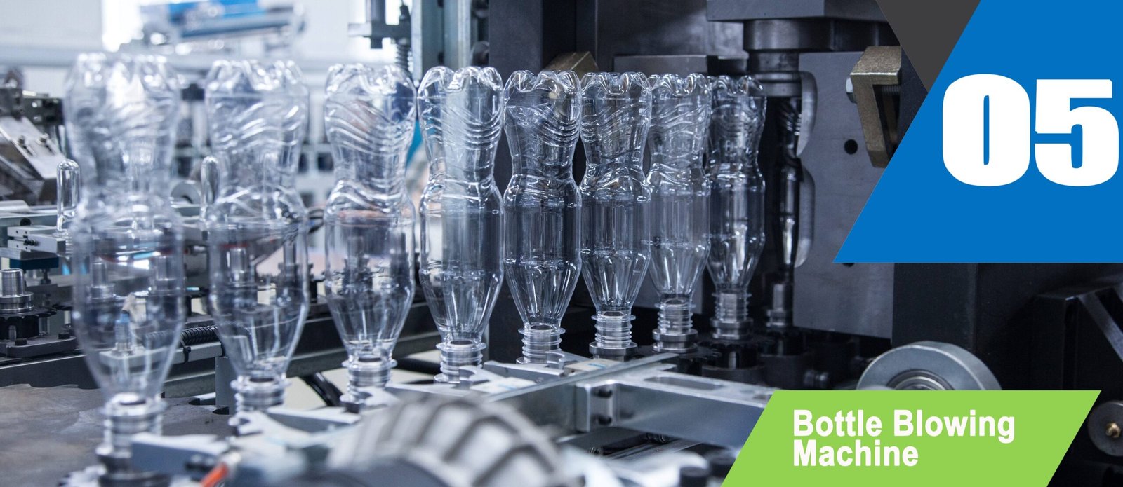
Industrial Machinery Assembly & Workshop: turnkey bottling line step 05 automatic bottle blowing machine
6. Case Study: A Juice Plant Splitting Treatment and Filling
A juice processor in South-East Asia had installed an HTST unit and a hot-fill line as two separate projects with two suppliers. Both performed to their own datasheets. Combined, the line could not reach its rated output without failing its own micro checks on a proportion of production.
- Product arriving at the filler colder than the temperature the hot-fill validation assumed
- Buffer tank sized by intuition, with residence time longer than the process allowed
- Foaming at the filling valves when the line was pushed towards its rated speed
- Two suppliers, two scopes, and no single document defining the interface
- Log temperature at three points — treatment outlet, filling valve inlet and inside the filled container
- Insulate and shorten the product run between the two machines, and re-check the loss at running flow
- Recalculate buffer volume from the plant’s recorded stoppages instead of the drawing’s assumption
- Re-tune filling valves for laminar fill and reset the fill level for the actual product temperature
- Interface defined as written numbers: temperature, hold time, flow rate and fill level
- Foaming removed at the valve by fill method and level rather than by slowing the line
- Buffer residence time brought back inside the process limit, with a divert strategy replacing the extra volume
- A commissioning sequence written down and reused for the next line in the group
Nothing in that project required new technology. It required one document that treated the pasteuriser and the filler as one machine, and a commissioning sequence that measured the interface instead of assuming it.
Frequently Asked Questions
Design the Treatment and the Filler as One Line
Send your bottle drawing, container sample or target output. Our engineering team replies with a machine recommendation, mould assessment and factory-direct quotation within 24 hours.
Related Reading:
• Liquid Filling Machines — Hot Fill, Isobaric and Monobloc
• Hot Fill Lines for Juice and Tea
• Isobaric Filling for Carbonated Soft Drinks
• Cleaning the Circuit Where Treatment Meets Filling
• Laying Out a Combined Treatment and Fill Line
• Monobloc Rinsing, Filling and Capping on One Frame



