
Most preform projects choose the drive system last. The cavity count is fixed from the bottle programme, the tonnage follows from the projected area, the mould is quoted, and the hydraulic-versus-servo decision is left as a line item to be settled on price. That order is backwards. On a preform machine the drive determines how repeatably the injection profile can be followed, how much energy the machine consumes per thousand preforms, how much cooling water and floor space the power unit needs, and what the maintenance calendar looks like for the next ten years.
Get the drive wrong and the mistakes are expensive to undo. A machine bought on initial price alone can carry a higher energy bill than the interest on the difference, and a shop running three shifts will feel it every month. A drive that cannot hold a repeatable velocity profile will show up as weight scatter across cavities, which is precisely the defect that causes trouble in the blowing machine downstream and takes weeks to trace.
Servo vs hydraulic injection molding is therefore a decision about duty cycle and precision, not about brand preference. Sailwin has built PET preform injection machines for 15+ years, with 500+ machines delivered to 60+ countries, manufacturing under ISO 9001:2015 with CE marking and supporting installations with a 2-year machine warranty. The SW-P range covers 14 models from 170 to 5,500 kN, runs valve-gate hot runners up to 64 cavities, uses dedicated PET screws with far-infrared nano heater bands and offers the EUROMAP 67 robot interface. This guide sets out what each drive actually buys you, where hydraulics still wins, and how to decide by numbers rather than by habit.
Key Takeaways
- The drive decides repeatability, not just speed. A servo-driven injection axis follows the velocity profile the recipe asks for; a hydraulic axis follows it as well as the valve, oil temperature and pressure supply allow.
- Energy is where the payback lives. Servo drive on a preform machine can cut energy use by up to 30% against a comparable hydraulic machine, and the saving scales with shift pattern rather than with machine size alone.
- Hydraulics remain the right answer for some plants. High tonnage, very long holding phases, hot ambient conditions and a site with an existing hydraulic service capability can all favour a well-specified hydraulic machine.
Choosing a Drive System for a Preform Project?
Send your cavity count, cycle time target and shift pattern — Sailwin engineers return a machine recommendation with a drive comparison and energy estimate within 24 hours.
1. What the Drive Actually Determines
A preform machine executes a sequence: plasticise, inject at a controlled velocity, transfer to hold pressure, pack until the gate seals, cool, open, eject. The drive system is what delivers that sequence, and its characteristics appear in the part long before they appear in the utility bill.
The first characteristic is velocity repeatability. A preform weight is set largely by the point at which injection transfers to hold pressure and by how much material has entered the cavity by then. If the injection stroke decelerates inconsistently from shot to shot, weight moves with it. Servo-driven injection holds a commanded profile tightly because the axis is positioned directly; a hydraulic system reaches the same profile through valve response, oil compressibility and pressure dynamics, which is achievable but demands good valve hardware and disciplined oil temperature control.
The second characteristic is what happens to the energy that is not used. A hydraulic power unit with a fixed-displacement pump and a proportional valve delivers flow continuously and dumps the surplus as heat. That heat is not free: it is oil temperature rise, more cooling load on the chiller, more hydraulic oil degradation and a hotter machine hall. A servo system draws power close to what the motion needs, which is why the same production output can be achieved on materially less electricity.
The third characteristic is the shape of the maintenance calendar. Hydraulic machines concentrate wear in pumps, valves, seals, accumulators and oil, and the work is familiar to any maintenance team with a hydraulic background. Servo machines concentrate wear in motors, drives and mechanical transmission, and their hydraulics — where present, for example in a servo-hydraulic hybrid clamp — are much smaller. Which of those two calendars suits your plant is a real factor, and it is often decided by the skill set you already employ rather than by the technology itself.
Two secondary effects are worth counting as well. Noise and heat: a well-set servo machine is noticeably quieter and cooler, which matters in a plant with a rising labour cost attached to the working environment. And control granularity: on a machine whose PLC monitors 40+ parameters in real time, the value of that monitoring depends on the axes being able to hold what they are told to hold. Data is only useful when the machine can act on it.
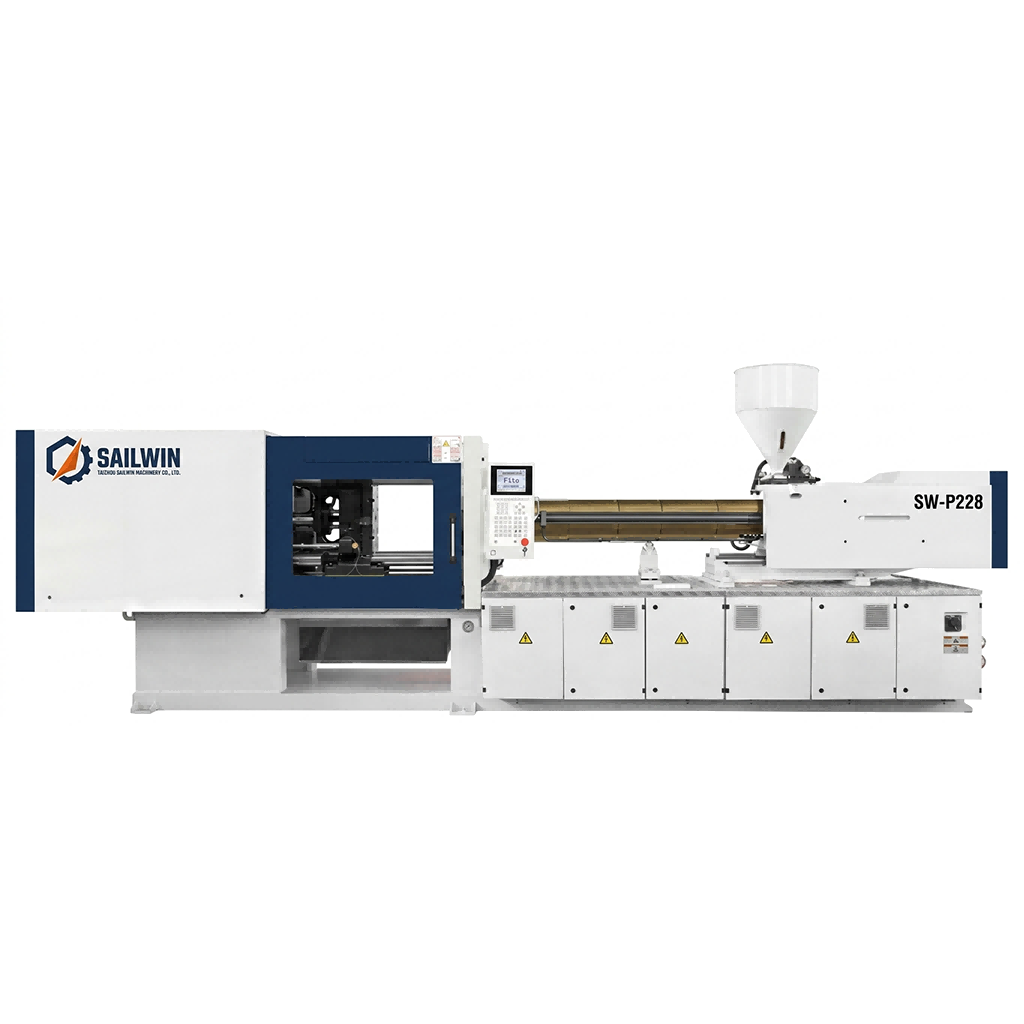
Precision Engineering & Core Components: sw p228 pet preform injection molding machine
2. Where a Hydraulic Machine Is Still the Right Answer
Servo drives are not universally better. There are configurations where a well-built hydraulic machine is the more rational purchase, and pretending otherwise leads buyers into a machine that is more expensive than the job requires.
High clamp tonnage with a relatively short injection requirement is the classic case. Clamp force is a pressure-times-area calculation, and generating a large force hydraulically remains efficient per unit of capital cost. On the largest preform and industrial container tools, the tonnage needed at the clamp can dominate the machine’s specification, and the hydraulic solution often still presents the better ratio of capability to price.
Low utilisation is the second case. If the machine runs one shift, energy saving is worth proportionally less, and the payback period stretches. A plant that needs one preform tool running eight hours a day, with frequent product changes and a modest output target, may never recover a servo premium through electricity alone — though it might still buy the servo machine for precision or for the absence of a hydraulic power unit in a clean room.
Existing capability is the third and most underrated case. A maintenance department that knows hydraulic systems well, stocks seals and valves, and can diagnose a pressure problem in an afternoon will keep a hydraulic machine running at high availability. The same team facing an unfamiliar drive and servo motor may be dependent on the supplier for every fault. Availability, not specification, is what determines real output.
There are also process arguments. Very long holding phases on thick, heavy preforms — large jars, wide-mouth containers with substantial wall sections — keep the machine in a low-flow, high-pressure condition for a large part of the cycle, which is a regime hydraulics handle competently. And in environments with extreme ambient heat and dust, a conventional hydraulic power unit can be easier to keep cool and to service than a cabinet full of drives.
3. Where Servo Drive Earns Its Premium
Servo drive earns its money in three places: energy, precision and the controllability of the process window.
Energy first, because it is the argument that survives a finance review. Servo-driven machines are specified to reduce energy consumption by up to 30% against comparable hydraulic machines, because the drive draws power in proportion to the work demanded instead of dumping unused flow as heat. That is a Sailwin figure for its servo-equipped machines, and it is measured on the machine’s own consumption rather than on the plant’s total utility bill, which will also include drying, cooling and compressed air.
Put that into an illustrative comparison. Take a machine averaging 45 kW on a hydraulic drive and a servo equivalent drawing 30% less, or about 31.5 kW — these numbers are a worked example, not a machine specification. Over a two-shift year of 4,000 production hours the difference is roughly 54,000 kWh, and over a three-shift year of 6,000 hours it is roughly 81,000 kWh. Multiply by your own tariff and by the years you intend to keep the machine, and the comparison stops being about technology and becomes an ordinary capital calculation. Note also that the saving does not appear only in the electricity line: less heat rejected into the machine hall means less chiller load, which is a second, smaller saving that rarely gets counted.
Precision second. On a preform machine with a valve-gate hot runner, cavity-to-cavity weight variation is a headline quality metric, and the injection axis is one of the two inputs that decides it — the other being the hot runner’s own balance. A servo axis reproduces the velocity profile more consistently, which narrows the weight spread and reduces the amount of gate-timing trim needed to bring the slowest cavity into line. On a 48 or 64 cavity tool that difference compounds: less trim means less risk that a recipe change for one cavity disturbs the others.
Controllability third, and it is the one that grows over time. A dedicated PET screw with far-infrared nano heater bands and PID temperature control holding the setpoint to ±1 °C gives a stable melt, but a stable melt is only useful if the injection axis can then follow the profile that the stable melt requires. Servo drive also makes it practical to run profiles that a hydraulic machine would struggle to reproduce — a staged filling profile for a preform with a difficult gate area, or a gentle packing ramp for a thick jar preform — and to store those as recipes rather than as an operator’s judgement.
| Criterion | Hydraulic drive | Servo drive | What to verify |
|---|---|---|---|
| Velocity repeatability | Good when valves and oil temperature are well controlled | High; profile is positioned directly by the axis | Ask for a weight scatter study across cavities at production cycle time |
| Energy consumption | Baseline; surplus flow is rejected as heat | Up to 30% lower on Sailwin servo-equipped machines | Request measured consumption at a defined cycle, not a motor nameplate rating |
| Heat and noise | Oil cooling load and continuous pump noise | Lower rejected heat; quieter hall | Check chiller load and measured sound level at the operator position |
| Maintenance profile | Pumps, valves, seals, oil changes, filtration | Drives, motors, transmission; smaller hydraulics where used | Compare against the skills your team already has, and spare-part lead times |
| Process window | Adequate for a stable, single-product programme | Wider; multi-stage profiles are practical and repeatable | Test the profile you actually intend to run, on your own tool |
| Capital cost | Lower | Higher | Calculate payback from your tariff and hours, not from a rule of thumb |
The right test is not “which drive is more advanced”. It is “how many hours a year will this machine run, and how tight does the weight have to be”. Those two answers decide the drive before the model number is chosen.
4. A Decision Framework by Duty Cycle and Product Mix
Four variables carry most of the decision: annual running hours, the weight tolerance the bottle programme requires, the number of formats the line must handle, and the capital budget. Set them out for your own project and the drive usually selects itself.
| Your situation | Likely best fit | Reason |
|---|---|---|
| Three shifts, one or two formats, tight weight tolerance, high cavity count | Servo | Maximum running hours maximise the energy saving, and precision protects the downstream blow process |
| One or two shifts, modest output, price-sensitive project | Hydraulic | Energy saving is diluted by low hours; capital can be spent on cavity count or tooling instead |
| Wide format range with frequent changeovers, or a clean-room-class area | Servo | Recipe recall and profile repeatability reduce changeover risk; no large oil reservoir in a hygiene-critical hall |
| Very high tonnage or thick-wall products with long hold phases | Evaluate both | Hydraulic clamp economics are strong at high tonnage, while the injection axis may still justify servo assistance |
| Existing hydraulic maintenance skill, remote site, long spare-part lead times | Hydraulic | Availability beats specification; a machine the team can fix today outproduces a better one waiting for a technician |
Two refinements are worth knowing. First, the premium is not always all-or-nothing: a servo-hydraulic machine puts servo drive where precision is needed and hydraulics where force is needed, which is a legitimate middle path on large-tonnage projects. Sailwin’s range includes all-electric drive options on its extrusion blow moulding models such as the SW-60 to SW-90 series, which is the same engineering principle applied to a different process. Second, whatever the drive, the machine’s usefulness depends on the components around it: Siemens or Mitsubishi PLC control, FESTO air valves, SMC cylinders, Schneider electrical components and ABB equipment are all specified for serviceability and for the availability of spares over a ten-year horizon.
5. Case Study: A Plant Replacing a Hydraulic Machine
A beverage group in South-East Asia was replacing an ageing hydraulic preform machine. The plant ran three shifts, supplied its own blowing lines, and had spent two years chasing weight variation that it suspected came from the old machine’s hydraulic system.
- Weight variation between cavities blamed on the mould, then on the resin, without evidence for either
- Hydraulic oil temperature rising through the day, with the resulting process drift visible in the weight chart
- Energy cost per thousand preforms rising faster than production volume
- Replacement decision complicated by an existing team whose skills were entirely hydraulic
- Separate the two variables first: stabilise the hot runner and mould cooling before changing any injection setting
- Quantify the drift by logging weight across a full shift against oil temperature, not by sampling one hour
- Compare a servo machine against a hydraulic replacement on the plant’s own tariff and shift pattern
- Plan training and spare-part stocking before delivery, not after the first breakdown
- Drift traced to hydraulic heat in the old machine, with the evidence recorded before the replacement decision
- Servo drive selected on hours and tariff, with the payback shown as an arithmetic calculation rather than a claim
- Melt stability improved by combining far-infrared nano heater bands with PID control at ±1 °C
- Operator training and a wear-part stock list agreed at the same time as the machine order
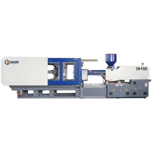
Industrial Machinery Assembly & Workshop: sw p300 pet preform injection molding machine
6. Specification Questions That Settle the Argument
Whichever drive you choose, these are the questions that force the supplier to commit to numbers rather than adjectives, and they apply equally to a hydraulic and a servo machine.
What is the measured weight scatter across cavities at production cycle time? Ask for the spread as a percentage of nominal mass, on a tool with the cavity count you intend to buy, at the cycle time you intend to run. This single number tells you more about whether the drive suits your product than any description of the control architecture.
What does the machine consume at that operating point? Not a motor nameplate rating, not a sum of installed power, but measured consumption at a defined cycle, cavity count and resin. Ask whether the figure includes the temperature control units, and get it in writing.
How is the profile programmed and how is it locked? Recipes should be recalled by product, editable only with a defined access level, and exportable for backup. A recipe that lives in one operator’s head is a production risk regardless of the drive technology behind it.
What monitoring and diagnostics are exposed? A machine with real-time monitoring of 40+ parameters is far more useful if the data can be trended against part weight than if it can only be read on a screen. Ask what is logged, for how long and in what format.
What is the delivery, installation and after-sales commitment? Sailwin machines ship in 30 to 45 days for standard configurations and 45 to 60 days for custom builds, undergo a full-load factory acceptance test before shipment, and are installed and commissioned on site in 3 to 7 days. Common wear parts ship within 48 hours and remote engineering support runs 24/7. Those commitments matter more on a three-shift machine than any difference in the drive’s characteristic curve.
Need a Drive Comparison for Your Own Numbers?
Send your annual running hours, electricity tariff, cavity count and weight tolerance — Sailwin engineers return a machine configuration with a payback calculation within 24 hours.
Frequently Asked Questions
Choose the Drive, Then Choose the Machine
Send your bottle drawing, container sample or target output. Our engineering team replies with a machine recommendation, mould assessment and factory-direct quotation within 24 hours.
Related Reading:
• PET Preform Injection Molding Machines — SW-P Series, 170 to 5,500 kN
• Where Injection Moulding Energy Actually Goes
• Matching Tonnage and Cavity Count to a Preform
• PET Screw and Barrel Design for Preform Moulding
• Servo Versus Hydraulic Drive on Blow Moulding Machines
• High-Cavity Valve-Gate Hot Runner Behaviour



