
Water treatment is specified as a utility and paid for as a process. A treatment train designed only to deliver a flow rate at an acceptable cost will produce water that passes a basic test and then behaves unpredictably in the filler: dosing that drifts, conductivity that moves between shifts, residual disinfectant that varies, and complaints that cannot be traced to any single machine. The filling line is blamed because it is the last thing the water touches.
The cost of treating water as a utility shows up in three places. Product quality becomes variable, because the water going into the bottle is not constant even when the treatment plant is running. Chemical and energy consumption rise, because a system sized for flow rather than for quality tends to be over-dosed to compensate. And assurance becomes difficult, because a plant that cannot state the water quality at the filler inlet per shift cannot answer a customer question about a batch.
Sailwin has built filling equipment for 15+ years, with 500+ machines delivered into 60+ countries, CE marking, ISO 9001:2015 manufacturing and a 2-year whole-machine warranty. Our filling lines include 3-in-1 rinse-fill-cap monoblocs with 180° flip grippers for bottle rinsing, laminar flow filling valves, constant magnetic torque capping, isobaric and hot fill configurations, and dedicated 5-gallon water lines, all in SUS304/316L construction with a 24-hour full-load factory acceptance test. This article explains how the treatment train interacts with the filler, what has to be measured per shift, and how to specify the interface so water quality is a controlled parameter rather than an assumption.
Key Takeaways
- Start from a full raw water analysis, not a hardness figure. Hardness alone cannot tell you whether you need softening, reverse osmosis, or degassing, and it says nothing about bromide, silica or organic load.
- Water quality at the filler inlet is a process parameter. Treat it like fill volume or capping torque: measured, trended and with defined limits, not simply supplied.
- Residual disinfectant needs a defined endpoint. UV leaves no residual; ozone does, and it needs reaction and decomposition time before the water reaches a bottle.
Send Your Water Analysis for Line Integration Review
Share the raw water report, target product and required output — Sailwin engineers return the treatment train, storage and hygiene requirements for your filling line.
1. The Treatment Train and What Each Stage Does
A bottling plant’s treatment train is assembled from a small number of stages, and the classic error is to order them by convention rather than by what the raw water actually contains. A softener placed where reverse osmosis is needed removes hardness and leaves everything else in the water; a carbon filter installed for taste can become a microbiological growth site if it is not sized and regenerated properly.
| Stage | What it removes or changes | Line interaction to plan for |
|---|---|---|
| Media and carbon filtration | Turbidity, chlorine, some organics and taste compounds | Backwash demand and drain capacity; carbon as a growth site if regeneration is neglected |
| Softening | Hardness (calcium and magnesium) by ion exchange | Regeneration salt handling, brine disposal, and the fact that it does not reduce dissolved solids |
| Reverse osmosis | Dissolved solids, most ions and a large proportion of organic material; typical rejection rates in industrial systems are in the region of 90–99% of dissolved solids, depending on design and feed water | Feed pressure and pump load, concentrate handling, temperature sensitivity of permeate quality |
| Ultraviolet disinfection | Microbiological load, without leaving a residual in the water | Transmission depends on water clarity; dose monitoring and lamp ageing must be recorded |
| Ozone | Microbiological load with a residual effect in storage and distribution | Needs contact and decomposition time; requires residual monitoring at the filler, and attention to bromide in the raw water |
| Mineral dosing | Adds calcium, magnesium or other salts to reach a target profile | Dosing accuracy and mixing; must be upstream of the point where quality is sampled, not downstream |
Read the third column as the integration checklist. Every stage has a consequence for the filling line that is not about water chemistry: backwash demand needs drain capacity, RO concentrate needs disposal, ozone needs time that the layout has to provide, and mineral dosing needs measuring points downstream. These are layout and instrumentation decisions, and they are far cheaper to make on a P&ID than on site.
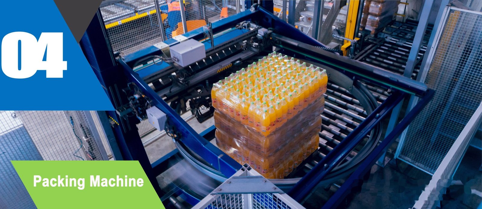
Precision Engineering & Core Components: turnkey bottling line step 04 shrink wrapping packing machine
2. Where Treatment Meets the Filler: Storage, Pressure and Hygiene
Between the treatment plant and the filler there is usually a storage tank, a distribution pump and a length of pipework. This is the part of the system where water quality is most easily lost, because treated water is aggressive and unprotected: it has little or no disinfectant residual if the train ends in UV, and it is an excellent growth medium the moment it sits still. Tank turnover, tank hygiene and distribution design therefore matter as much as the treatment stages themselves.
Three design rules follow. First, storage should be sized for turnover rather than for convenience: a tank that holds a full shift of production at low throughput is a standing microbiological risk, whatever the treatment train does upstream. Second, distribution pipework should be designed for cleaning, with a defined CIP route, no unnecessary branches and no low points that hold water — the same rules that apply to the filling machine’s own product circuit. Third, the water supply pressure at the filler inlet should be specified and controlled, because filling accuracy and valve behaviour depend on a stable supply.
Where the line includes a monobloc with 180° flip grippers for bottle rinsing, the rinse water is a separate consideration from the product water. A rinse stage is a hygiene function and its water quality and pressure have to be specified independently; on 5-gallon lines this matters even more, because the container itself is cleaned as part of the process and the internal rinse is a quality-defining step rather than a pre-treatment. Both should be reflected in the layout rather than resolved by tapping the nearest convenient line.
3. What to Measure, and How Often
A treatment system that is not measured is a system that is assumed to be working. The measurements below are the ones that turn water quality into a controlled parameter: they are all simple, and together they let a plant state what went into the bottle. Limits should be taken from the drinking-water and bottled-water rules that apply in the market you sell into, and from the product specification for any mineral profile you claim.
| Checkpoint | Why it is measured here | Typical frequency |
|---|---|---|
| Conductivity or total dissolved solids | Fastest indicator of a treatment stage drifting or a membrane losing performance | Continuously, with a shift record |
| Residual disinfectant | Confirms ozone or other residual is at target at the filler, not just at the dosing point | At start-up and at defined intervals per shift |
| Hardness | Detects softener exhaustion before it reaches the bottle | Per shift, and after each regeneration |
| pH and turbidity | Process stability and a check on filtration performance | Per shift |
| Ultraviolet dose and lamp hours | A lamp past its useful life still looks lit but no longer disinfects | Continuous monitoring with lamp hours logged |
| Microbiological testing | The result that actually matters, taken at the points the market rules require | According to the schedule your market and customers require |
| Mineral profile (if claimed) | A labelled mineral content is a specification, so dosing drift is a labelling risk | Per batch, plus verification of dosing pump calibration |
Water is the only ingredient in the bottle that the plant produces itself. That makes its quality a manufacturing parameter with a record, not a supply specification on a contract.
4. Case Study: Water Quality That Varied Between Shifts
A water bottling plant found that product taste complaints clustered on particular shifts, while every treatment stage passed its scheduled checks.
- Taste complaints clustered by shift with no corresponding treatment alarm
- Quality checks taken at the treatment plant outlet, not at the filler inlet
- Storage tank sized for a full shift, so residence time varied with production rate
- Measuring points relocated to the filler inlet and to the tank outlet, so both ends of the distribution were visible
- Residual disinfectant and conductivity trended per shift rather than recorded as a pass or fail
- Tank turnover reviewed against production rate, with distribution cleaned on a defined CIP route
- Shift-to-shift variation became visible as a trend instead of a complaint pattern
- Water quality entered the batch record, so a batch could be defended with data
- Treatment and filling treated as one process with shared responsibility for the specification
Scenario based on a Sailwin customer project; site-specific figures available on request during engineering review.
5. Integrating Treatment With the Filling Line
The integration work is mostly about interfaces, and it is best done on a single P&ID that both the treatment supplier and the filling supplier work from. Sailwin filling lines are built in SUS304/316L with CIP capability, and every machine is tested at full load for 24 hours before shipment, which is the point at which supply pressure, flow stability and rinse performance can be observed under real conditions rather than under test-bench conditions.
- Agree the water specification at the filler inlet. Not at the treatment outlet, and not as a range so wide that any quality passes.
- Design storage for turnover, not for buffer. A smaller tank that is continuously refilled is a better microbiological proposition than a large one that is half empty for most of the day.
- Specify supply pressure and flow at the filler. Filling valve behaviour and accuracy depend on a stable feed, and a pump curve is not a specification.
- Define the CIP route for the distribution system. Pipes that the cleaning circuit cannot reach are pipes that will eventually be opened up in response to a complaint.
- Separate rinse water from product water in the specification. On monoblocs with flip grippers and on 5-gallon lines, the container rinse is a quality step with its own requirements.
- Put water quality data into the batch record. Treatment values at the filler inlet, per batch, alongside fill volumes and capping torque, so a batch can be described completely.
- Test the interface during acceptance, not after. Run the line at full output with the treatment plant in normal and degraded modes, and confirm the filler behaves as specified.
Installation and commissioning for a Sailwin line is normally completed in 3–7 days on site, with common wear parts shipped within 48 hours and remote engineering support at 7×24. The same support logic applies to the water side of the plant: a treatment system with instrumentation that reports into the same control layer as the filler is diagnosable, while one whose data lives in a separate panel ends up being investigated by two different teams who never compare notes.
Integrate Water Treatment With Your Filling Line
Send the raw water analysis, product specification and required output — Sailwin engineers return the treatment train, storage sizing and instrumentation points for your line.
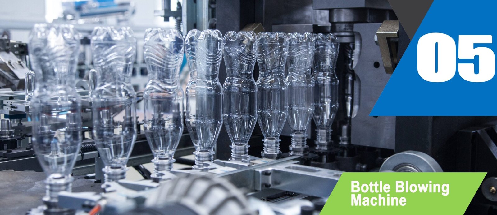
Industrial Machinery Assembly & Workshop: turnkey bottling line step 05 automatic bottle blowing machine
6. Frequently Asked Questions
Treat Water Quality as a Process Parameter of the Filling Line
Send your bottle drawing, container sample or target output. Our engineering team replies with a machine recommendation, mould assessment and factory-direct quotation within 24 hours.
Related Reading:
• Filling Machines: Monobloc, Isobaric, Hot Fill and 5-Gallon Lines
• 5-Gallon Water Filling Lines
• CIP Cleaning on Filling Machines
• Bottle Rinsing: Methods and Machine Integration
• Filling Accuracy Standards and How to Hold Them
• Filling Line Layout Design



