
Utility shortfalls almost never look like utility shortfalls. They look like a filler that will not hold its rated speed, a capping torque that drifts in the afternoon, a CIP cycle that finishes without reaching temperature, or a rejection rate that rises on hot days. Each of those has a machine-shaped symptom and a plant-services cause, which is why the investigation usually starts in the wrong place.
The cost of under-specifying utilities is not only the shortfall itself. Compressed air leaks and oversized steam systems are paid for continuously, and a cooling water supply that cannot hold its temperature forces operators to compensate by slowing the line, which then gets recorded as a machine limitation. Because utilities are shared across the plant, a filling line’s requirement is often reduced to a flow figure on a schedule with no specification of pressure stability, quality or simultaneity.
Sailwin has built filling equipment for 15+ years, with 500+ machines delivered into 60+ countries, CE marking, ISO 9001:2015 manufacturing and a 2-year whole-machine warranty. Our lines include 3-in-1 rinse-fill-cap monoblocs, isobaric and hot fill configurations, CIP-capable SUS304/316L construction and dedicated 5-gallon water lines, all tested at full load for 24 hours before shipment. This article sets out what a filling line actually demands from steam, compressed air, cooling water and power, and how to specify those demands so the line runs at its rated output.
Key Takeaways
- Specify simultaneity, not just totals. A line that needs steam for CIP, air for capping and cooling water at the same time cannot be served by adding up individual peak figures.
- Pressure stability matters more than nominal pressure. A compressor rated at the right pressure but cycling on a small receiver produces the same symptom as an undersized one.
- Air quality is a product-contact decision. Where compressed air touches the bottle or the product, its filtration and dew point belong in the hygiene specification, not only in the maintenance schedule.
Send Your Line Layout for a Utilities Review
Share the machine list, output target and CIP regime — Sailwin engineers return steam, air, water and power requirements with simultaneity assumptions stated.
1. Why Utility Shortfalls Appear as Line Speed Losses
Most utility problems are second-order effects. Compressed air pressure does not fall below the level at which a valve fails to actuate; it falls below the level at which the valve actuates crisply. The machine keeps running, the cycle gets marginally longer, and the loss is a few per cent that nobody attributes to air. The same happens with cooling water: a supply that is a couple of degrees warm does not stop anything, it slows a heat transfer step and extends a dwell.
This is why utility data should be logged alongside machine data rather than in a separate services logbook. When line output and cooling water temperature are plotted on the same axis, the correlation is usually visible within a week. Sailwin machines monitor 40+ parameters through the PLC in real time and hold PID temperature control loops to ±1°C, so machine-side variation can be excluded when investigating a cause that turns out to be on the plant side.
There is also a demand-side question that is usually ignored. Utility consumption scales with how the line is operated, not only with what it is. Servo drive technology on modern machines can reduce energy consumption by up to 30 per cent compared with fixed-speed alternatives, and a line that is stopped with utilities still running — conveyors idling, air blowing, rinse water open — pays for its own inefficiency continuously. Utility specification and operating discipline are the same project.
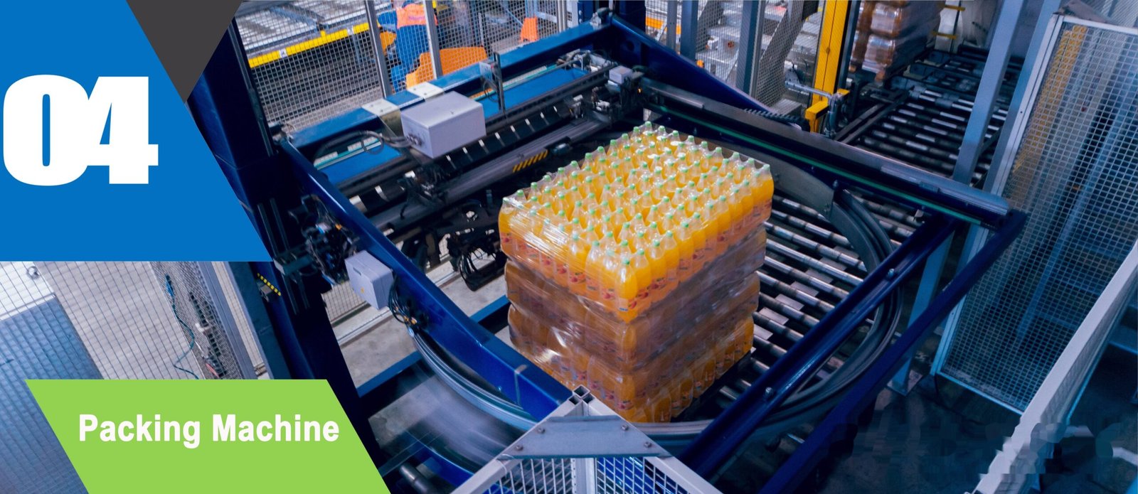
Precision Engineering & Core Components: turnkey bottling line step 04 shrink wrapping packing machine
2. Steam: Hot Fill, CIP and Pasteurisation
Steam appears on a bottling line for three purposes, and each has a different demand profile. Hot filling needs a controllable, stable product temperature at the filler. CIP needs a defined volume of water at a defined temperature for a defined time. Pasteurisation, where it is used, needs a sustained heat load at a controlled temperature. Only the first of these is a continuous demand; the other two are large and intermittent, which is what makes simultaneity the key sizing question.
| Demand | Nature of the load | What to specify |
|---|---|---|
| Hot fill product heating | Continuous, with tight temperature stability; typical hot fill product temperatures for juice and tea sit in the region of 85–95°C as an industry-typical range | Steam pressure and flow at the maximum line rate, plus control resolution at the heat exchanger |
| CIP heating | Large and intermittent; cleaning solutions are typically held in the 70–85°C region as an industry-typical range | Peak load during cleaning, and whether production runs concurrently on another line |
| Pasteurisation | Sustained load at controlled temperature across the whole production run | Load at maximum rate, plus a defined response to a temperature excursion |
| Condensate and steam quality | Continuous; affects heat transfer and equipment life | Steam dryness, filtration and treatment, and trap maintenance discipline |
Two specification traps are worth naming. First, a boiler sized for average demand will fail during simultaneous cleaning and production, because cleaning is a step change rather than an average. Second, an undersized condensate return or a failed steam trap produces a wet steam condition that looks like a capacity problem but is actually a heat-transfer problem — the boiler has the capacity, and the heat is not reaching the process.
3. Compressed Air: Quality, Pressure and Silent Losses
Compressed air is the most expensive utility on most sites per unit of energy delivered, and the one most often treated as free. On a filling line it drives valve actuation, cylinder movements, capping heads, blow-off and sometimes container handling. Sailwin machines are built around SMC cylinders and valves on the pneumatic side, with plant air supplied at low pressure in the region of 8–10 bar. Where a plant also runs PET blow moulding, that equipment needs a separate high-pressure supply in the region of 30–40 bar, and the two systems should not be confused in the utility schedule.
Quality is where compressed air changes from a power question into a hygiene question. If air is used for blow-off on a bottle neck before capping, for container drying, or anywhere it can contact the product, then its filtration and dryness belong in the sanitary specification: particulate and coalescing filtration, an appropriate dew point for the application, and in food-contact applications oil-free air. A plant that has specified a sterile filling environment and then blows unfiltered air into the container has addressed the visible risk and left the invisible one.
Pressure stability deserves more attention than nominal pressure. A compressor that cycles on a small receiver produces pressure fluctuation, and fluctuation produces inconsistent valve and cylinder behaviour: capping torque that drifts with supply, actuators that move slightly late. The symptoms are intermittent, which makes them expensive to diagnose. Adequate receiver volume, sensible pressure band settings and leak elimination do more for line stability than a larger compressor in most plants — and leaks, typically at fittings and quick couplings, are paid for every hour the plant is running.
4. Cooling Water and Electrical Load
Cooling water appears in several places on a bottling line and is usually shared with the rest of the plant, which is exactly why it fails quietly. Carbonated filling, hot fill cooling after the filler, capping head cooling and any product cooling all draw from the same chilled supply. Sailwin specifies chilled water at 8–12°C for mould cooling circuits on its PET equipment, and the same discipline applies to line cooling: the number that matters at the machine is the supply temperature and its stability, not the chiller’s rated capacity.
| Utility | Typical line demand pattern | Specification detail that prevents trouble |
|---|---|---|
| Chilled water | Continuous during production; peaks during hot fill cooling | Supply temperature and stability at the machine, flow per circuit, and return temperature rise |
| Compressed air | Continuous with frequent short peaks at each actuation | Pressure band, receiver volume, filtration and dew point for any product-contact use |
| Electrical load | High at start-up when several drives and heaters energise together | Connected load, starting method, voltage stability at the panel, and generator behaviour on changeover |
| Drain and effluent | Large intermittent discharge during cleaning | Drain capacity for CIP and rinse peaks, temperature limits and chemical compatibility |
On the electrical side, the specification that prevents problems is rarely the total connected load; it is the starting method and the voltage stability at the machine panel. A line whose drives start together draws a transient that may dip voltage enough to disturb other equipment, and a plant running on a standby generator may find that a filling line which runs perfectly on mains behaves differently on generated supply. Both are worth testing rather than assuming, because both produce symptoms that look like machine faults.
Utilities are the only part of a filling line where the machine’s performance depends on equipment the machine supplier never sees. That is exactly why they need to be specified with the same precision as the machine itself.
5. Case Study: A Line That Slowed Down Every Afternoon
A beverage plant reported that its filling line lost speed consistently in the afternoon, and had attributed the pattern to operator performance on the later shift.
- Output loss correlated with time of day and with ambient temperature, not with any machine alarm
- Cooling water and compressed air data held in a services logbook, never compared with line data
- Utility schedule listed total flows with no specification of pressure or temperature stability
- Utility measurements brought into the same logging as machine data so the two trends could be compared
- Supply temperature and pressure recorded at the machine rather than at the plant room
- Simultaneity of demand reviewed across production and cleaning, including periods of concurrent operation
- The afternoon loss became an identifiable utility condition rather than a shift-performance question
- Specification moved from nominal flow figures to temperature and pressure stability at the machine
- Services and production now review the same data, which shortened the next investigation considerably
Scenario based on a Sailwin customer project; site-specific figures available on request during engineering review.
6. Sizing and Documenting Utilities Properly
A utility schedule that works has four columns: the demand, the value, the simultaneity assumption, and the condition at the machine. Without the last two, the schedule is a wish list. The checklist below is what to insist on before a line is ordered, and it applies whether the line is a 3-in-1 monobloc, a hot fill configuration, a 5-gallon water line or a combination of several machines.
- State demand at the machine, not at the plant boundary. Pressure and temperature at the point of use are what the process sees.
- Include the cleaning regime in the simultaneity case. CIP, rinse and production often overlap in real plants even when the schedule says they do not.
- Separate product-contact air from general plant air. Filtration and dew point requirements follow the hygiene specification where air can reach the bottle or the product.
- Measure cooling water return temperature as well as supply. The rise tells you whether the circuit is removing heat, which is the number that explains slow cooling.
- Check starting behaviour and generator operation. Test the line on standby supply before it matters, not during the first power interruption.
- Bring utility data into the same log as machine data. A correlated trend answers in a week what a separated logbook cannot answer in a year.
- Verify the utilities at acceptance, not at commissioning. Sailwin tests every line at full load for 24 hours before shipment and completes installation and commissioning in 3–7 days on site, and the utility conditions should be part of that test.
Sailwin lines are built in SUS304/316L, support CIP and hot fill configurations, and are backed by common wear parts shipped within 48 hours and remote engineering support at 7×24. Utility discipline is the other half of that reliability: a well-built line running on an unstable air supply or a warm cooling circuit will underperform, and the machine will be blamed for it.
Size Your Line Utilities Correctly From the Start
Send the machine list, output target, cleaning regime and site supply data — Sailwin engineers return the utility schedule with simultaneity assumptions and point-of-use conditions.
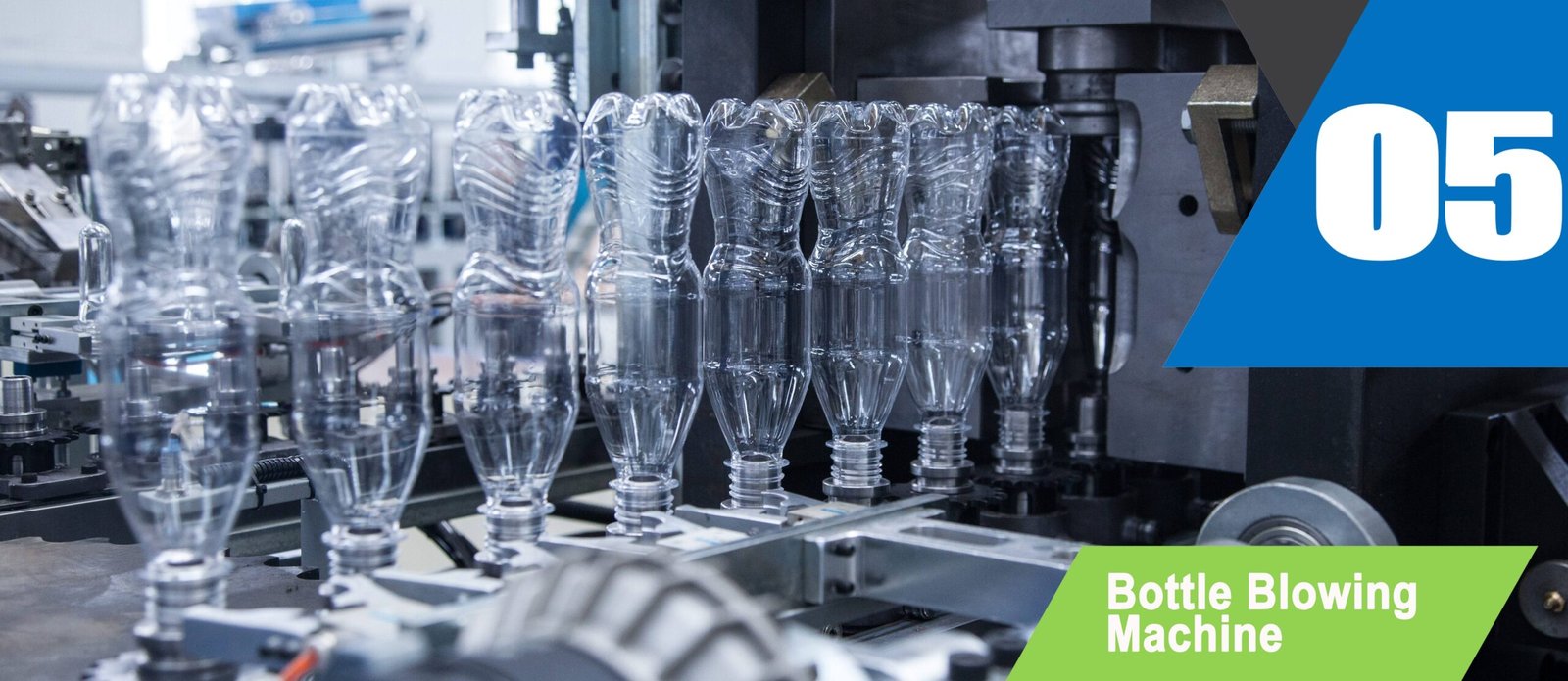
Industrial Machinery Assembly & Workshop: turnkey bottling line step 05 automatic bottle blowing machine
7. Frequently Asked Questions
Specify Utilities With the Same Precision as the Machine
Send your bottle drawing, container sample or target output. Our engineering team replies with a machine recommendation, mould assessment and factory-direct quotation within 24 hours.
Related Reading:
• Filling Machines: Monobloc, Isobaric, Hot Fill and 5-Gallon Lines
• Hot Fill Juice and Tea Filling
• Pasteurisation and Filling Line Integration
• Filling Line Layout Design
• CIP Cleaning on Filling Machines
• PLC and Automation Architecture for a Bottling Line



