
Updated: 2026 Engineering Standard · By Sailwin Technical Team
Air Recovery Systems in PET Blow Molding: How to Recycle 30 Bar Exhaust Air to Save Energy
In modern high-speed PET bottle manufacturing, operating high-pressure air compressors is by far the largest electrical utility expense on the factory floor. Generating 30 to 40 bar compressed air consumes immense electrical horsepower. Yet in conventional blow molders, after the bottle is formed, this valuable high-pressure air is simply vented into the atmosphere through noisy exhaust mufflers—literally blowing thousands of dollars in utility bills out the window every hour.
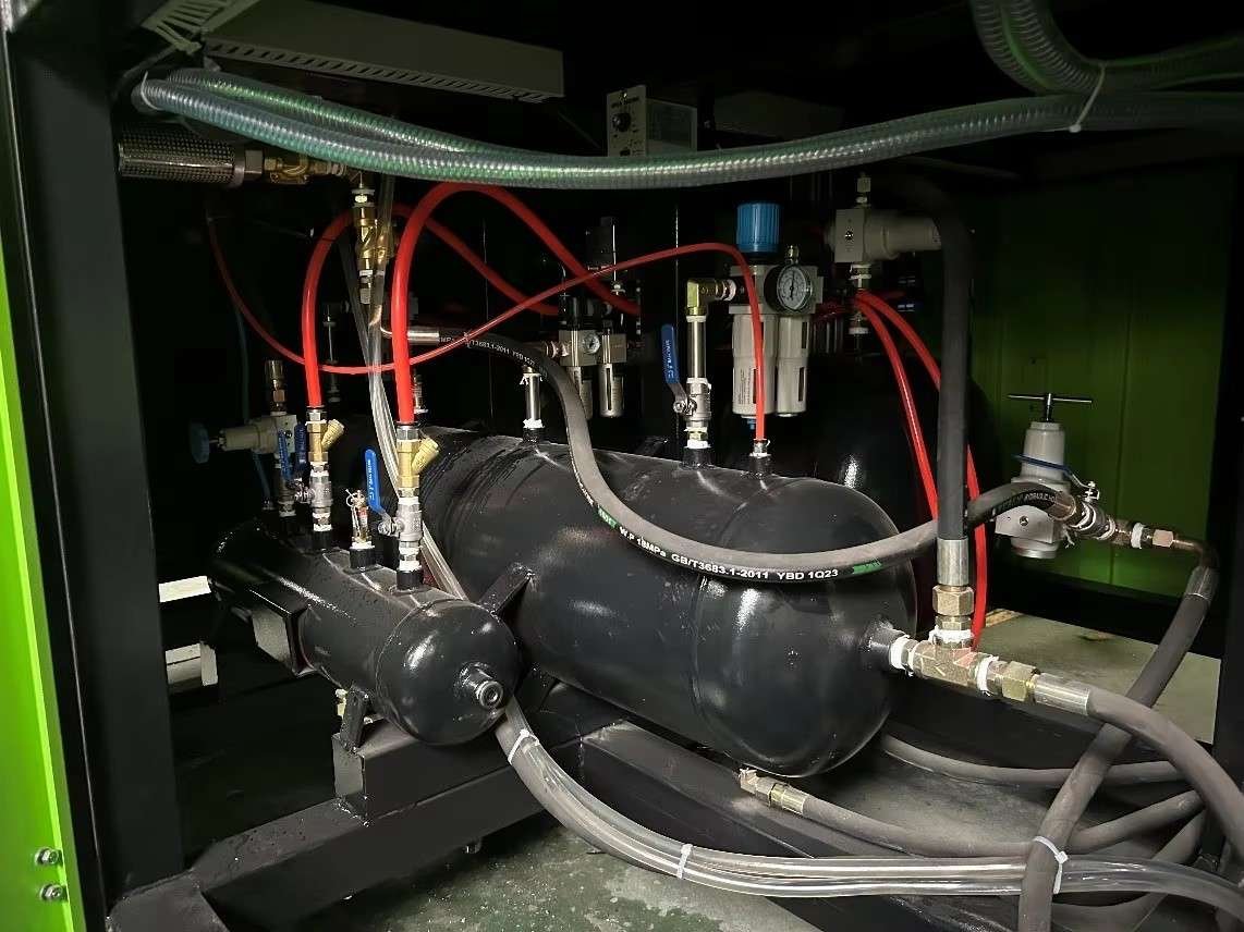
Overcoming this energy waste requires modern air recycling technology. On Sailwin automatic PET blow molding machines, integrated Air Recovery Systems (ARS) capture the initial burst of high-pressure exhaust air and redirect it into intermediate storage tanks.
This engineering guide details the pneumatic circuitry, dual-stage exhaust valve manifolds, and quantified kilowatt-hour savings achieved by recovering high-pressure air for machine pneumatic movements and downstream factory utility lines.
Key Engineering Takeaways
- Recapture 30% to 45% of High-Pressure Air: A 2-stage exhaust valve system diverts the first phase of exhaust air (from 35 bar down to 12–15 bar) into a dedicated receiver tank before final venting.
- Zero-Cost Low-Pressure Utility: Recovered 12-bar air is regulated to 7–8 bar, completely powering machine platen cylinders, preform elevators, and downstream packaging conveyors without running low-pressure compressors.
- Compressor Load Reduction: Air recovery reduces running hours and duty cycles on 30-bar booster compressors, cutting equipment wear, oil filter maintenance, and electrical peak demand charges.
Want to Reduce Your Air Compressor Electricity Bill?
Submit your hourly bottle output and compressor specifications for a tailored kilowatt-hour air recovery savings calculation.
1. Working Principle & Pneumatic Circuitry of Air Recovery Systems
Pneumatic Energy Law: The first 50% of bottle exhaust air holds over 70% of the stored pneumatic energy. Capturing it before atmospheric venting powers your entire low-pressure plant for free.
Review the dual-stage air recovery valve sequence below:
| Cycle Phase | Bottle Pressure Range | Active Solenoid Valve | Destination of Air | Energy Recovery Function |
|---|---|---|---|---|
| Phase 1: High Blow | 30 – 38 bar | High Blow Valve | Bottle Mold Cavity | Inflates plastic against chilled mold details. |
| Phase 2: Recovery Exhaust | 35 bar down to 12 bar | Recovery Exhaust Valve | Intermediate Air Recovery Tank | Captures 40% of air volume at 12–15 bar pressure. |
| Phase 3: Final Exhaust | 12 bar down to 0 bar | Final Exhaust Valve | Silencer Muffler to Atmosphere | Vents remaining low-energy air to ensure 0-bar mold opening. |
| Phase 4: Plant Redistribution | Regulated 7.0 – 8.5 bar | Pressure Reducing Manifold | Machine Cylinders & Downstream Line | Supplies 100% of pneumatic utility air for conveyors and cylinders. |
Sailwin Customer Case Study: Beverage Bottler Saves $32,600 Annually in Compressor Power with Sailwin ARS
How a commercial water factory running an 8,000 BPH packaging line reduced electrical load by retrofitting Sailwin Air Recovery Technology.
- A 75 kW high-pressure air compressor and a 22 kW low-pressure compressor operated at 100% duty cycle, driving up factory utility bills.
- Peak electrical demand surcharges strained operating margins during summer months.
- Exhaust air noise in the blow molding room exceeded 92 dBA.
- Equipped Sailwin 6-cavity linear blow molder with integrated 2-stage Air Recovery System.
- Redirected recovered 14-bar air through a 1,000L receiver tank to power machine platen movements.
- Shut down the separate 22 kW low-pressure air compressor completely.
- Low-pressure compressor power consumption reduced to zero (100% powered by recovered air).
- High-pressure compressor unload time increased by 22%, saving $32,600 USD annually.
- Blowing room ambient noise dropped from 92 dBA to under 74 dBA.
Data source: Sailwin Energy Audit & Electrical Billing Verification #SW-ARS-2026, 2026.
Frequently Asked Questions
SAILWIN MACHINERY · FACTORY-DIRECT PACKAGING SYSTEMS
Cut Bottling Energy Costs with Sailwin Air Recovery Technology
Sailwin linear and rotary blow molders are engineered with native air recovery manifolds. Request energy savings proposal today.
Explore Integrated Packaging Machinery on Sailwin:
• PET Preform Injection Molding Machine – High-speed 140T to 550T systems for multi-cavity bottle preform lines.
• PET Water Bottle Blowing Machine – Linear automatic servo stretch blow molding equipment.
• Liquid Filling Machine & Bottling Line – 3-in-1 rotary monoblocs for drinking water and beverage factories.
• HDPE Extrusion Blow Molding Machine – Industrial continuous blow molding systems for jerrycans and drums.
• Need technical plant advice? Contact our engineering team for free turnkey consultation.



