
Cooling is the longest single event in preform moulding and the one most often treated as a utility rather than a design feature. On a typical preform cycle, cooling accounts for more than half the cycle time — an industry-typical proportion, not a figure specific to any machine — which means a mould with unbalanced or inadequate cooling does not just produce worse preforms. It produces them more slowly, cavity by cavity, shift after shift, while every other part of the machine is capable of more.
The cost of ignoring it is measurable in three places. Cycle time is set by the slowest-cooling cavity, so one badly cooled position slows the whole tool. Dimensional quality drifts, because PET that is cooled unevenly shrinks unevenly and the preform becomes oval or thicker on one side. And the tools that suffer most are the multi-cavity tools that were bought precisely for productivity, since they multiply both the number of circuits and the difficulty of keeping them balanced.
Sailwin has built injection moulding machines for 15+ years, with 500+ machines delivered into 60+ countries, CE marking, ISO 9001:2015 manufacturing and a 2-year whole-machine warranty. The SW-P series covers 14 models from 170 kN to 5,500 kN, supports 64-cavity valve-gate hot runner tooling with a dedicated PET screw and far-infrared nano heating coils, and controls machine temperatures with PID loops to ±1°C. This article explains how core and cavity cooling circuits actually work, where imbalance comes from, how it shows up in the preform, and how to verify a circuit before a mould is signed off.
Key Takeaways
- Cooling uniformity is a specification, not a preference. The tool runs at the speed of its slowest cavity, so a single unbalanced circuit sets the cycle time for all 64 positions.
- Flow regime matters more than water temperature. Turbulent flow transfers heat far faster than laminar flow, so circuit bore, length and parallel paths should be designed together.
- Measure flow per circuit, not per manifold. A manifold that receives the correct total volume can still starve individual cavities, and ovality is usually the first symptom.
Review Your Preform Mould Cooling Layout
Send the mould drawing, cavity count, core geometry and available water supply — Sailwin engineers return circuit recommendations and a verification plan.
1. Why Preform Mould Cooling Design Sets the Cycle
A preform leaves the injection stage at melt temperature and has to be cool enough to eject without distorting. That cooling happens almost entirely by conduction: heat travels from the PET through the mould steel and into the water in the circuit. Every step in that chain is a resistance, and the design question is which one dominates. Thin walls and small cores stack two resistances in series — the PET itself and the steel — before the water ever sees the heat.
This is why preform moulds are not cooled like a flat part. On the cavity side, the steel around the preform body is close to the melt and relatively easy to cool with conventional drilled or milled circuits. On the core side, the geometry is a thin long probe inside a hot tube, and heat has to travel down the core wall to reach the water. Core cooling is therefore the limiting factor on most preform tools, and it is decided by two things: how effectively the coolant reaches the inside of the core, and how turbulent that coolant flow is when it gets there.
The practical consequence is that cycle time and preform quality are the same discussion. Reduce cooling time and you reduce the cycle; reduce it unevenly and you introduce ovality, internal stress and inconsistent acetaldehyde in the same change. Sailwin PET injection machines provide the stable process platform for that discussion: 14 SW-P models from 170 kN to 5,500 kN, 64-cavity valve-gate hot runner support, and PID temperature control to ±1°C on the machine temperature loops, so cooling behaviour can be measured against a repeatable melt condition.
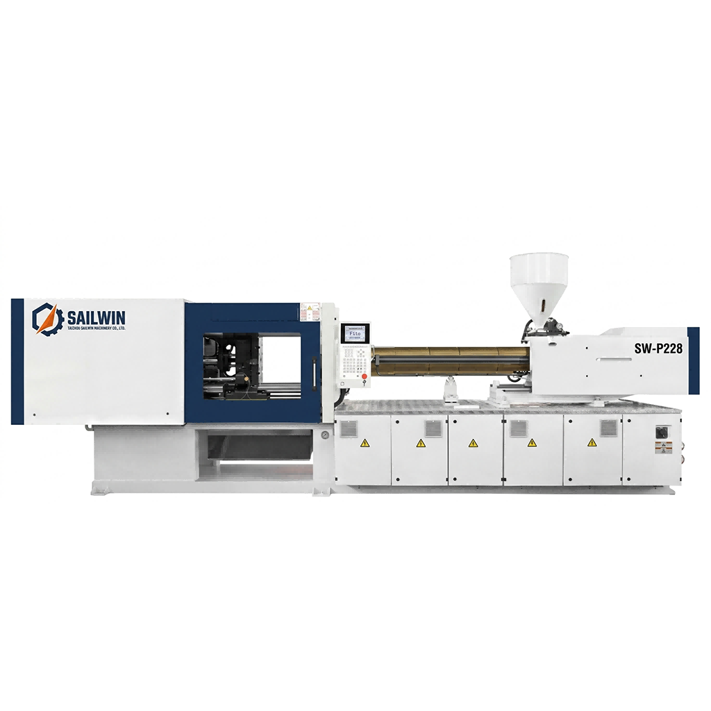
Precision Engineering & Core Components: sw p228 pet preform injection molding machine
2. Core Side Cooling: Bubblers, Conductivity and Flow Regime
The core of a preform mould is cooled by a bubbler tube or a similar internal flow device that directs coolant to the tip of the core and returns it along the core wall. The physics is straightforward: water enters through a small-diameter tube, reaches the hottest area near the preform tip and gate end, then travels back along the annular gap between the tube and the bore, picking up heat from the core steel on the way out. Almost all of the heat transfer happens in that annular gap, which makes the gap dimension the most important number on the drawing.
Flow regime decides how efficiently that gap works. Laminar flow, in which water moves in smooth layers, insulates the wall with a slow-moving film of water right against the steel. Turbulent flow breaks that film up and can raise heat transfer by an order of magnitude — a standard heat-transfer result, not a machine-specific claim. Engineering practice is normally to design cooling channels for turbulent flow at the flow rates the plant can actually deliver, which in typical mould cooling circuits means aiming for water velocities of roughly 1.5 to 3 m/s as an industry-typical range. The exact figure depends on bore diameter and circuit length, but the principle is universal: if the water is not turbulent, the circuit is being wasted.
Core material adds a second variable. Higher-conductivity alloys transfer heat from the preform surface into the cooling water more quickly than conventional tool steels, which shortens cooling time but changes wear behaviour and the way the core withstands the injection pressure cycle. The trade-off should be made deliberately, at the design stage, together with the steel selection for the rest of the mould.
| Core cooling variable | Effect on cooling | How a fault shows up |
|---|---|---|
| Bubbler tube position and length | Sets where the coldest water reaches inside the core | Longer cycle; tip or gate-area overheating |
| Annular gap dimension | Controls velocity for a given flow rate | Laminar flow; poor heat pick-up despite adequate volume |
| Flow rate per core | Determines heat removed per unit time | Cavity-to-cavity cycle variation across the tool |
| Core material conductivity | Sets how fast heat reaches the water | Long cooling time; tip whitening on thick sections |
| Water temperature stability | Keeps the driving temperature difference constant | Drift over a shift; rejects that appear in batches |
3. Cavity Side Circuits and Why Balance Is the Real Problem
Cavity-side cooling looks easier and fails differently. Drilled or milled circuits around the preform body are usually generous, but on a multi-cavity tool they are connected through manifolds and distribution plates, and that is where balance is lost. Water follows the path of least resistance, so on a series circuit the first cavity in the chain receives the coldest water and the last receives water that has already absorbed heat from everything before it. On a parallel manifold, small differences in bore, fitting restriction or circuit length decide which cavities receive their share and which are starved.
The number to control is flow per cavity, measured at each circuit, not total manifold volume. A manifold can deliver exactly the designed total flow while individual cavities receive wildly different amounts, which is why a tool can pass a flow test at the pump and still produce cavity-to-cavity weight variation. Series circuits, parallel circuits and independent temperature zones are all legitimate answers; what matters is that the arrangement was chosen deliberately and can be verified on the bench rather than inferred from a pressure gauge.
A mould with 64 cavities is not a mould with one cooling system; it is 64 cooling systems that happen to share a pump. The tool will run at the speed of the worst of them.
4. How Cooling Imbalance Shows Up in the Preform
Uneven cooling rarely announces itself as an obvious defect. It appears as a pattern — a variation between cavities, a difference between the two halves of the same preform, or a drift that develops over a shift. Because the same symptoms can come from the hot runner, the drying system or the machine, the diagnostic value of cooling data depends on comparing positions rather than inspecting single parts.
| Observation | Cooling-side cause | What to check first |
|---|---|---|
| Oval cross-section | Different shrinkage on two sides of the wall | Flow balance between opposite circuits on the same cavity |
| Cavity-to-cavity weight spread | Starved circuits cooling differently along the tool | Flow per circuit measured individually, not manifold total |
| Whitening or haze near the tip | Core tip not cooled early enough before ejection | Bubbler tube length and position relative to the tip |
| Sticking or ejection marks | Core-surface temperature above the ejection threshold | Return water temperature rise across the core circuit |
| Drift over a shift | Rising supply temperature or flow loss from fouling | Chiller stability and circuit differential pressure |
| Acetaldehyde variation between cavities | Thermal history differences during cooling | Cavity-level temperature data logged over a full run |
The last row is the one that surprises plants most. Acetaldehyde generation in PET depends on thermal history, so a cavity that cools differently from its neighbours can produce a chemically different preform from the same resin and the same machine settings. Because Sailwin machines monitor 40+ parameters through the PLC in real time, cavity-level trends can be logged against machine data instead of being reconstructed from a complaint that arrives three weeks later.
5. Case Study: Cooling Imbalance on a Multi-Cavity Preform Tool
A preform producer running a multi-cavity tool could not shorten its cycle without triggering ovality and cavity-to-cavity weight variation, and had assumed the limit was the machine.
- Cycle time reductions at the machine triggered ovality and weight spread across cavities
- Cooling verified only as total manifold flow; individual circuit flows never measured
- Core-side circuits assumed adequate because return water temperatures looked reasonable
- Flow measured at every circuit and mapped cavity by cavity, with the starved positions identified
- Bubbler tube length and position reviewed against the core geometry and the tip location
- Supply temperature stability confirmed at 8–12°C before any process change was attempted
- Cooling moved from a utility assumption to a measured, cavity-level design variable
- Cycle reduction attempted only after balance was established, so gains held instead of being reverted
- Circuit flow became part of the mould sign-off record alongside dimensions and gate data
Scenario based on a Sailwin customer project; site-specific figures available on request during engineering review.
6. Verifying a Cooling Circuit Before Mould Sign-Off
Cooling problems are cheapest to fix on the bench and most expensive to fix in production, so verification belongs in the tool trial rather than in the first week of running. The starting condition for that verification is a stable supply: Sailwin specifies chilled water at 8–12°C for mould cooling circuits, and the machine’s temperature loops hold ±1°C, which means any variation you then measure is a property of the mould and not of the plant.
- Measure flow at every circuit individually. Record the value against cavity number and compare it with the design intent, not with a total for the manifold.
- Record supply and return temperature for each group. A small rise means heat is being removed; no rise on one circuit usually means no flow through it.
- Check for trapped air and inadequate venting. Air pockets behave like a blocked circuit and are the most common cause of a single cavity running hot.
- Establish the baseline at full cavity output, not at reduced setup speed. Cooling behaviour changes when every cavity is producing continuously, and a trial at half output proves nothing about the production condition.
- Document the baseline so it can be compared later. Circuit flows, temperatures and the resulting weight and ovality figures become the reference for every future fouling or cycle-time discussion.
Once that baseline exists, cycle optimisation becomes an engineering exercise rather than a gamble. Changes can be made one variable at a time, and the effect on preform quality can be attributed to the cooling change rather than to the resin, the dryer or the hot runner. Sailwin supports that work with full-load factory acceptance testing before shipment, on-site installation and commissioning in 3–7 days, common wear parts shipped within 48 hours, and remote engineering support at 7×24.
Get a Cooling Circuit Review for Your Preform Tool
Send the mould drawing, cavity count and core detail — Sailwin engineers return circuit balance recommendations and a verification checklist for your tool trial.
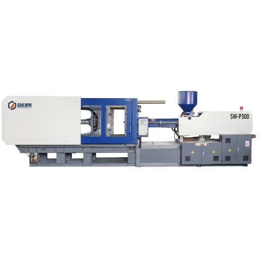
Industrial Machinery Assembly & Workshop: sw p300 pet preform injection molding machine
7. Frequently Asked Questions
Treat Preform Cooling as a Design Variable, Not a Utility
Send your bottle drawing, container sample or target output. Our engineering team replies with a machine recommendation, mould assessment and factory-direct quotation within 24 hours.
Related Reading:
• Injection Molding Machines: SW-P Series 170–5500 kN
• Preform Cooling Time: How to Set It
• Preform Cycle Time Optimisation
• Preform Mould Steel Selection
• 64-Cavity Hot Runner Preform Mould Technology
• Selecting a Preform Injection Molding Machine



