
In industrial packaging and custom plastic bottle production, a sophisticated high-speed blow molding machine is only as capable as the tooling mounted between its platens. Packaging manufacturers frequently invest tens of thousands of dollars in high-tonnage machinery, only to experience chronic operational bottlenecks: sluggish cycle times caused by poor mold thermal cooling, unremovable bottom flash caused by dull pinch-off steels, parting line mismatch, and container warpage that prevents leak-proof capping. The blow mold is not an interchangeable commodity — it is a high-precision thermodynamic heat exchanger and mechanical shear tool that directly dictates container wall distribution, cycle efficiency, and structural rigidity.
Mastering the engineering fundamentals of blow mold design allows brand owners, contract packagers, and plant engineers to slash container development lead times, optimize polymer grammage, and extend tooling operational lifespans to millions of cycles. This comprehensive technical guide details the mechanical trade-offs between aircraft-grade aluminum, pre-hardened mold steel, and beryllium copper inserts, breaks down the 6-step custom mold manufacturing workflow from 3D CAD modeling to factory sampling, establishes a comprehensive machine compatibility verification checklist, and provides an actionable Request for Quotation (RFQ) framework to ensure your custom tooling integrates flawlessly into your production floor.
| Tooling Material Class | Thermal Conductivity (W/m·K) | Rockwell Hardness (HRC) | Typical Mold Production Life | Primary Manufacturing Application |
| Aircraft Aluminum (QC-10 / 7075-T6) | 130 – 160 (Ultra-Fast Cooling) | HB 150 – 175 (~28 HRC) | 3.0 – 5.0 Million Cycles | High-speed PET water, beverage, and edible oil bottle stretch blow molds. |
| Pre-Hardened Steel (P20 / 718H) | 29 – 34 (Moderate Cooling) | 30 – 36 HRC | 5.0 – 8.0 Million Cycles | Extrusion blow molds for HDPE jerrycans, detergent jugs, and 20L chemical carboys. |
| Stainless Steel (420 / S136) | 20 – 25 (Lower Cooling) | 48 – 52 HRC (High Polish) | 8.0+ Million Cycles | Corrosive polymers (PVC, flame-retardants), optical cosmetic jars, and medical vials. |
| Beryllium Copper (BeCu Inserts) | 105 – 130 (High Heat Dissipation) | 38 – 42 HRC | High Wear Inserts | Critical pinch-off inserts, handle pinch blocks, and bottle neck ring chilling zones. |
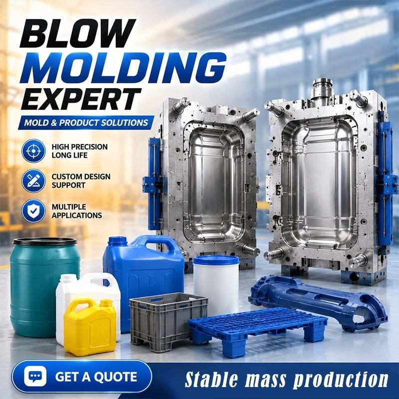
Why Precision Mold Engineering Is as Important as Machinery
In high-speed production, minor design oversights within the mold cavity propagate into severe manufacturing failures:
- Cycle Time Bottlenecks: Over 70% of total blow molding cycle duration consists of mold cooling time. An improperly cooled steel mold adds 2.0 to 4.5 seconds of dwell time per cycle compared to an engineered aluminum mold with conformal cooling channels, reducing annual plant output by up to 25%.
- Dull Pinch-Off Flash Defects: In extrusion blow molding machines, the mold pinch-off must cleanly weld the molten parison while cutting away excess tail flash. Inadequate pinch-off land width creates thick, sharp bottom tails that fail UN container drop tests and jam automated de-flashing stations.
- Bottle Neck Ovality and Capping Leaks: The neck thread area must maintain strict dimensional tolerances (±0.15mm). If mold neck cooling rings are poorly engineered, thread shrinkage causes ovality, leading to induction foil seal failures and commercial beverage leakage during transport.
The 6-Step Custom Mold Development Workflow: From 3D CAD to Production
Developing custom blow molds requires a disciplined engineering sequence to ensure the finished container meets volume, top-load strength, and aesthetic specifications:
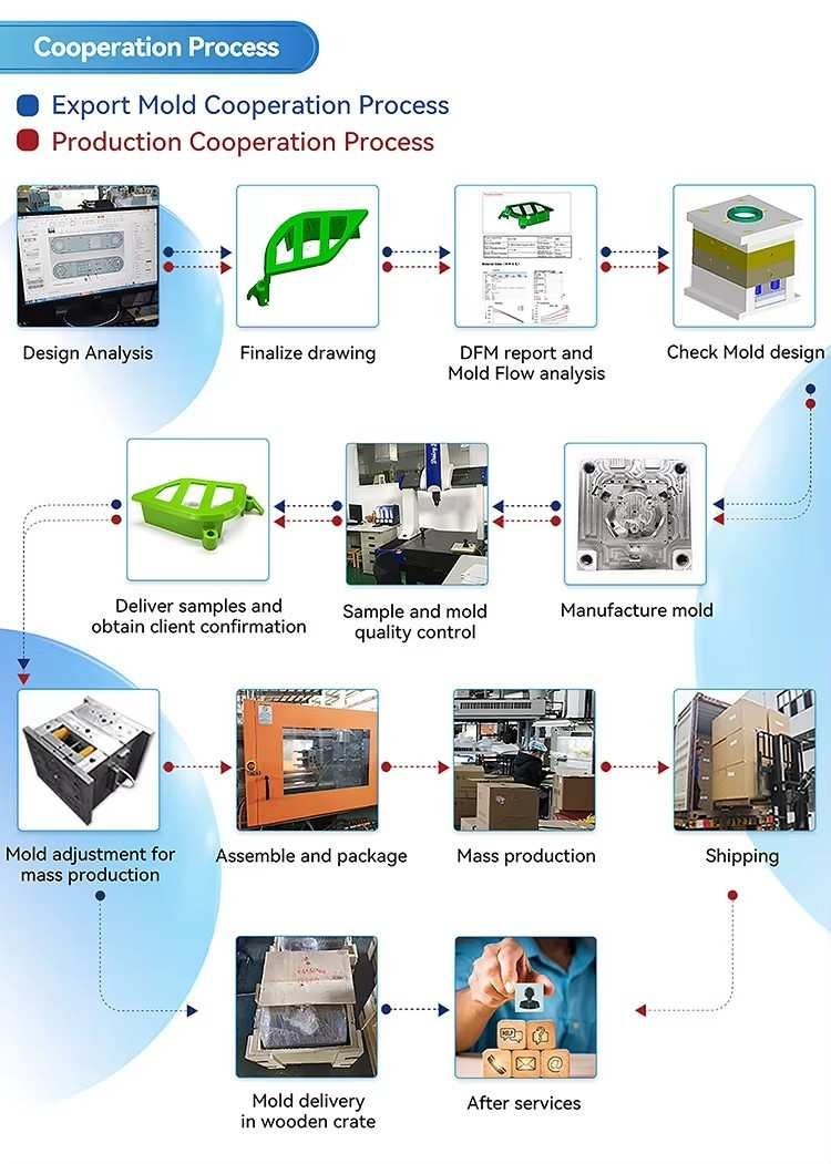
Step 1: Container Concept & Design for Manufacturability (DFM)
The client supplies a 2D sketch, 3D file (.STEP / .IGES), or an existing physical sample for 3D laser scanning. Sailwin engineers perform DFM analysis: checking draft angles, wall thickness stretch ratios, label panel recess depth, and stacking rib placement to ensure clean demolding.
Step 2: Rheological & Mold Thermal Simulation (CAE)
Using advanced finite element analysis (FEA) and mold flow software, engineers simulate parison stretch and inflation. The simulation detects thin spots around container corners and verifies that conformal water channel circuits provide uniform temperature distribution across the entire bottle geometry.
Step 3: Precision CNC Machining & Mirror Polishing
Tooling blocks are milled on high-speed 5-axis CNC machining centers running at 24,000 RPM to achieve micro-fine surface finishes. Mold cavities undergo automated EDM spark erosion for embossed logos and manual diamond compound polishing to reach optical SPI-A2 mirror finishes.
Step 4: Micro-Venting & Pinch-Off Steel Hardening
Micro-vent holes (0.2mm diameter) are precision-drilled along parting line seams and petaloid base valleys. For extrusion blow molds, hardened A2 or D2 tool steel pinch-off blades (58–62 HRC) are precision-fitted into the cavity base to ensure crisp tail shearing.
Step 5: Factory Sampling & T1 Container Verification
The mold is mounted on our in-house test blow molders for T1 sampling. Sample containers are measured for fill capacity, wall thickness distribution via ultrasonic gauge, neck thread pitch, and top-load compressive strength.
Step 6: Final Hard Coating & Global Shipping
Following customer sample approval, aluminum molds receive specialized nickel-Teflon or hard anodized coatings to enhance wear resistance and corrosion protection, followed by precision crating for international export dispatch.
Have a New Bottle Concept or Need Replacement Tooling?
Upload your 3D CAD drawing (.STEP/.IGES) or physical sample parameters to Sailwin’s mold engineering division. Our tooling engineers generate a comprehensive DFM manufacturability evaluation and itemized mold quotation within 24 hours.
Core Mold Engineering Fundamentals Every Buyer Should Know
Precision container functionality depends on adhering to strict kinematic and thermodynamic design rules:
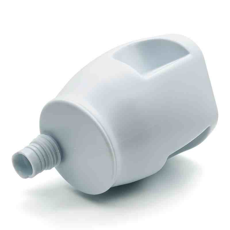
1. Draft Angles for Clean High-Speed Demolding
To prevent container scuffing and demolding hesitation on automated pick-and-place robots, mold cavity sidewalls require minimum draft angles: 1.5° to 2.5° per side for smooth polished surfaces, and 3.0° to 4.5° per side for textured, etched, or leather-grain surfaces.
2. The Pinch-Off Geometry: The Secret to High-Strength Seams
In HDPE container blow molding, the bottom pinch-off must perform two conflicting tasks: fuse the parison halves into a continuous, hermetic polymer weld, and cleanly cut the waste flash. Sailwin molds utilize a precision double-angle relief profile:
- Land Width: Calibrated to 0.8mm – 1.2mm depending on container wall thickness.
- Relief Pocket Angle: 30° to 45° clearance angle with a flash dam pocket to absorb extruded polymer without hydraulic platen push-back.
- Pinch Blade Hardness: Vacuum-hardened tool steel or beryllium copper inserts prevent blade dulling over millions of clamp strikes.
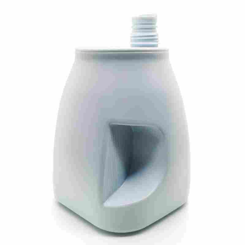
3. Complex Geometries: Integrated Handles & Recessed Grips
Designing containers with built-in hollow handles (such as 5L detergent bottles or stackable jerrycans) requires specialized slide-action tooling. The mold must incorporate pneumatic or hydraulic slide cores that advance to pinch the handle eyelet before mold inflation, and retract prior to platen opening.
4. Cavity Identification & Regulatory Markings
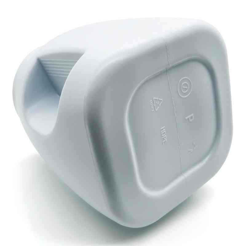
Every commercial mold must incorporate interchangeable date code stamps, cavity identification numbers, material recycling codes (e.g., SPI Resin Code #1 for PET, #2 for HDPE), and food contact logos permanently machined or insert-mounted into the mold base plate.
Tooling Material Selection: Aluminum vs Steel vs Specialty Alloys
Choosing the correct tooling alloy requires balancing thermal conductivity against wear longevity and production volume:
- Choose Aircraft Aluminum (7075-T6 / QC-10) When: Manufacturing high-speed PET stretch blow molded bottles. Aluminum dissipates heat 4.5 times faster than steel, significantly reducing cycle times. With nickel-PTFE plating, aluminum molds easily achieve 3 to 5 million bottle cycles.
- Choose Pre-Hardened Mold Steel (P20 / 718H) When: Manufacturing heavy-duty extrusion blow molded drums, multilayer coextrusion containers, or packaging utilizing abrasive post-consumer recycled (PCR) resins where pinch-off parting lines encounter heavy shear forces.
- Choose Hybrid Tooling (Aluminum Body + Beryllium Copper Inserts) When: Demanding maximum PET stretch blow molding speeds. Installing BeCu inserts around high-heat neck finish zones and base push-up petals delivers the ultimate combination of thermal dissipation and wear resistance.
Machine Compatibility Verification Checklist
Before releasing a custom mold for manufacturing, verify that physical mold dimensions match your target machinery specifications:
| Machinery Compatibility Dimension | Verification Standard / Tolerance | Risk of Misalignment |
| Platen Clamping Bolt Hole Pattern | Verify machine platen T-slot or tapped hole layout matches mold backplate exactly. | Mold cannot mount; requires emergency platen drilling. |
| Mold Thickness (Shut Height) | Must sit within machine minimum and maximum mold thickness envelope. | Tonnage toggle cannot lock over, or platen stroke cannot close. |
| Mold Opening Stroke Clearance | Opening daylight must exceed container outer diameter + bottom tail clearance + 50mm. | Blown container cannot be ejected or extracted by robotic arm. |
| Blow Pin / Stretch Rod Center Distance | Multi-cavity center-to-center pitch must match blow pin or parison die head spacing exactly. | Stretch rod strikes mold cavity edges, destroying precision tooling. |
| Cooling Water Connection Ports | Check thread specifications (G 1/2", NPT, quick-release push-in connectors). | Hoses cannot connect; restricted water flow causes hot spots. |
How to Submit a High-Conversion Mold RFQ
To receive an accurate, rapid tooling quote from mold manufacturers, provide the following comprehensive project specifications:
- 3D CAD Product Model: Provide .STEP or .IGES files showing complete container geometry, including thread pitch, base push-up, and label panels.
- Target Raw Polymer: Specify PET, HDPE, PP, or Multilayer Co-Ex (including target container weight in grams and expected shrinkage rate).
- Neck Finish Standard: Detail the neck finish (e.g., PCO 1881, 29/25, 38mm Bericap, or 70mm wide-mouth jar specifications).
- Target Blow Molding Machinery: Specify the exact machine model, platen dimensions, clamping tonnage, and cavity count (e.g., 2-cavity, 4-cavity, or 6-cavity linear stretch molder).
- Annual Container Volume: State annual production quantities to determine whether aircraft aluminum or hardened P20 steel is most cost-effective.
Representative Tooling Engineering Benchmark: Shortening Development Cycles with DFM
(Representative industrial benchmark based on typical custom packaging tooling workflows)
Initial Engineering Challenge: A packaging brand attempting to launch an asymmetric 2.5-liter agrochemical jug with an integrated handle experienced repeated tooling redesigns. Legacy mold makers built prototype tooling without CAE simulation, resulting in severe handle web cracking and blow pin cutting ring misalignment during initial test runs.
Sailwin Tooling Intervention: Sailwin mold engineers executed comprehensive DFM and virtual parison inflation simulation prior to cutting metal. Simulation revealed localized parison over-stretching around the rear grip corner. Engineers modified the handle eyelet draft angle by +1.5° and repositioned cooling channels 4mm closer to the high-heat pinch seam.
Benchmarked Engineering Outcomes:
- Sampling Redesign Elimination: Sampling revisions were compressed from a typical 3–4 physical mold recut cycles down to a single T1 verification run.
- Lead Time Compression: Total tooling development from 3D model sign-off to certified mass production was shortened from standard 45-day industry timelines to 28 business days.
- Drop Test Performance: The finished container passed rigorous UN 1.8-meter hazardous material cold drop tests on the very first production trial under ISO 9001 certified manufacturing quality standards.
Ready to Engineer Precision Custom Tooling for Your Containers?
Send your 3D container drawings or project requirements to Sailwin’s mold engineering division. We deliver comprehensive DFM manufacturability evaluations, mold design drawings, and turnkey tooling quotes.
Frequently Asked Questions: Custom Blow Molding Molds
What is the typical lead time for manufacturing a custom blow molding mold?
Standard lead times for precision aircraft-grade aluminum PET bottle molds range between 20 and 30 business days from final 3D CAD approval to T1 sample dispatch. Complex extrusion blow molds featuring hydraulic slide-action handles or multiple parison heads typically require 35 to 45 business days.
Can a single mold body accommodate interchangeable neck or base inserts?
Yes. Sailwin molds can be engineered with modular interchangeable inserts. A master mold base can accept different neck finish inserts (e.g., swapping between 28mm PCO 1810 and 1881) or variable base push-up plates, allowing brand owners to produce multiple bottle variants without commissioning entirely new mold blocks.
How many bottle cycles can an aluminum PET blow mold produce before requiring overhaul?
High-grade 7075-T6 or QC-10 aircraft aluminum molds with electroless nickel or hard anodized coatings comfortably produce 3.0 to 5.0 million bottle cycles under proper chilled water maintenance and non-aggressive mold venting cleaning protocols.
What is Design for Manufacturability (DFM) in blow mold engineering?
DFM is a pre-manufacturing engineering audit that evaluates container 3D CAD models against blow molding physical constraints. DFM identifies problematic sharp interior radiuses, inadequate draft angles, excessive stretch ratios, and unvented corners before cutting tool steel, preventing expensive tooling recuts.
Why are beryllium copper inserts used in aluminum blow molds?
Beryllium copper combines the wear resistance and hardness of tool steel (38–42 HRC) with thermal conductivity close to aluminum (105–130 W/m·K). Installing BeCu along container pinch-off parting lines and neck chilling rings provides high impact durability while pulling heat away from thick plastic sections rapidly.
How do I maintain mold cooling water channels to prevent scale buildup?
Circulate demineralized, treated closed-loop chilled water through mold channels. Flush water circuits semi-annually with a mild sulfamic acid descaling solution to remove calcium carbonate scale; a 1mm scale buildup inside cooling channels cuts heat transfer efficiency by up to 30%.
Can Sailwin build molds to fit non-Sailwin blow molding machines?
Yes. Sailwin regularly engineers and exports precision custom molds tailored to fit all major international blow molding machinery platforms (including European, Japanese, and North American linear and rotary machines). Simply provide your machine platen drawings and clamping stroke specifications.
What files are required to initiate custom mold design?
Preferred formats are native 3D CAD files (.STEP, .STP, or .IGES). If 3D files are unavailable, high-resolution 2D dimensioned drawings (.PDF / .DWG) or an intact physical sample container for 3D optical laser scanning are sufficient to initiate engineering design.
Summary & Related Machinery Guides
Custom mold design is the critical link translating container creativity into profitable packaging production. Selecting the right alloy (7075-T6 aluminum for high-speed PET; P20/S136 steel for heavy-duty extrusion containers), enforcing strict DFM principles (1.5°+ draft angles, optimized pinch-off relief), and verifying platen mounting geometry ensures rapid cycle times, flawless container cosmetics, and tooling durability spanning millions of cycles.
To further advance your packaging plant operations, review our related technical resources:
- Blow Molding Machine Engineering Knowledge Hub — Sizing and operating industrial blow molding systems.
- PET Blow Molding Machine Series Catalog — Automatic 2-cavity to 6-cavity linear stretch platforms.
- Jerrycan Blow Molding Machine Solutions — Tooling and machinery for stackable jerrycans and oil jugs.
- Multilayer Coextrusion Blow Molding Series — Tooling for 2 to 6-layer high-barrier containers.



