
A preform production line layout is normally drawn around the machines. Each unit is placed where it fits, pipes are run between them, and the layout is signed off when the drawing has no clashes. The problem is that machines are the fixed cost and material flow is the recurring cost, and it is material flow that decides how much labour, forklift movement, drying energy and damaged product the plant will absorb every day for the next decade.
The penalties for a layout that ignores flow are cumulative rather than dramatic. A dryer placed on the far side of the aisle from the machine costs a few seconds of operator time per intervention, multiplied by every intervention in three shifts. Preform storage placed away from the blower turns the preform into a logistics item that needs handling, wrapping and transport, and every one of those steps introduces contamination and scuffing. Cooling circuits that are long because the chiller sits in the wrong corner cost pump energy and produce temperature gradients the process then has to fight.
Sailwin has built PET preform injection machines and bottle production equipment for 15+ years, with 500+ machines delivered to 60+ countries, manufacturing under ISO 9001:2015 with CE marking and supporting installations with a 2-year machine warranty. The SW-P injection range covers 14 models from 170 to 5,500 kN and runs valve-gate hot runners up to 64 cavities; the PET blow moulding range covers models from 2-cavity 2,800 BPH machines up to 8-cavity 16,000 BPH high-output models. This guide sets out how to arrange resin handling, drying, moulding, cooling, preform storage, blowing and packing as one flow, with the services and control points that make it work.
Key Takeaways
- Draw the material flow first, then place the machines. Resin in at one end and pallets out at the other, with no step repeated and no material crossing its own path.
- The preform store is a process buffer, not a warehouse. Its location and capacity decide whether blowing runs continuously or stops every time moulding does.
- Services dictate the layout more than floor area does. Compressed air at 30–40 bar, chilled water at 8–12 °C and drying air all lose performance with distance and every unnecessary bend.
Planning a Preform and Bottle Line Layout?
Send your target output, container range and available floor area — Sailwin engineers return a machine configuration with a services and layout assessment within 24 hours.
1. Material Flow Decides the Layout
Begin with a single line on paper: resin arrives, becomes a preform, becomes a bottle, becomes a pallet. Everything else in the layout exists to serve that line without interrupting it. Draw it as a flow with arrows before drawing a single machine footprint, and the layout problems announce themselves early — where material has to double back, where two flows cross, where a step needs manual handling because the machines are too far apart.
Three principles keep the flow honest. First, no repeated steps: if an intermediate product has to be picked up, wrapped, moved and unwrapped again, the layout has created a handling operation that adds cost without adding value. Second, no crossing flows: finished goods and raw material should not share an aisle, because the moment they do, the aisle becomes a bottleneck and a contamination route. Third, keep the reversible steps reversible: preforms are a natural buffer between moulding and blowing, so placing storage so that it can feed the blower from either direction gives the plant flexibility it will need as soon as one machine stops.
Then overlay the constraints that cannot be moved: building columns, overhead crane coverage, floor loading limits, the electrical room position, drainage runs and the tank farm or resin silo location. Whatever survives that overlay is your real layout envelope — and it is usually materially smaller than the available floor area, which is why layouts drawn from floor area alone fail on services.
Finally, plan for the “worst Tuesday” rather than for steady state. A preform machine that stops for maintenance, a blowing machine that is being changed over, a resin delivery that arrives early, a quality hold on one batch: each of these is a normal event, and the layout should allow the plant to keep producing through all of them. That is what the preform buffer, the reversible conveying and a second route to the packing area are actually for.
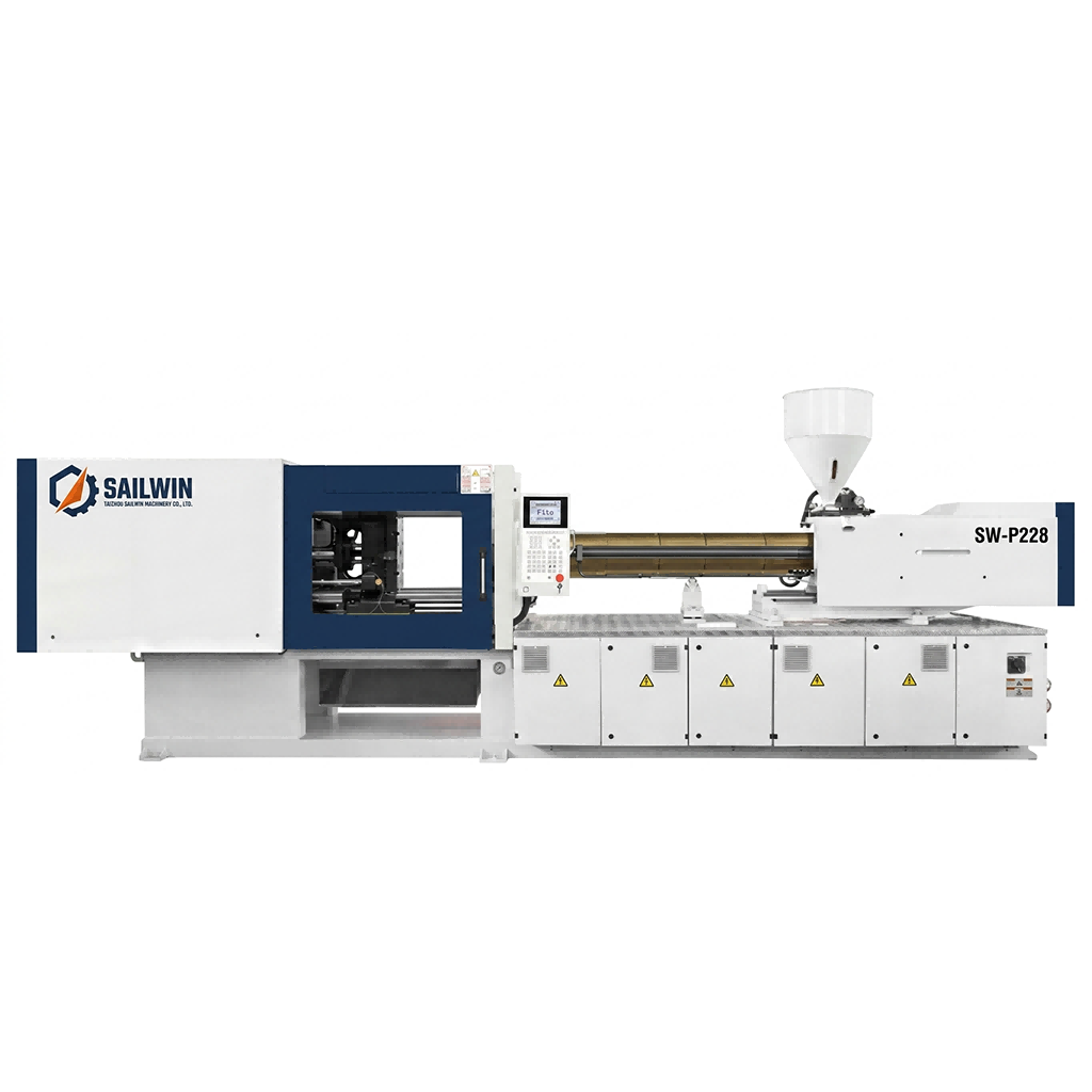
Precision Engineering & Core Components: sw p228 pet preform injection molding machine
2. Zoning the Plant From Resin to Pallet
A workable preform-and-bottle plant divides into six zones, and each one has an input, an output, a services requirement and a control point. Writing those four items down per zone turns the layout into a specification that can be built and audited, rather than a drawing that everyone interprets differently.
| Zone | Function | Services that matter most | Control point |
|---|---|---|---|
| Resin receiving and conveying | Silo or bag intake, conveying to dryers, colour and additive dosing | Conveying air (dry, oil-free), floor loading, access for delivery vehicles | Material identification and lot traceability at intake |
| Drying | Dehumidifying dryers sized per machine, with short feed runs | Regeneration air, electrical load, ambient temperature control | Dew point and drying time records per material |
| Injection moulding | Preform production, robot take-out, weight and dimension checks | Chilled water for mould and hydraulics, compressed air, crane coverage for mould changes | Process monitoring of 40+ parameters, weight sampling per cavity |
| Preform storage | Buffer between moulding and blowing, FIFO by lot, protection from contamination | Temperature stability, dust control, space for container handling without repacking | Lot identity and age; storage time limits |
| Blow moulding | Preform heating, blowing, leak and visual checks | Compressed air at 30–40 bar and 8–10 bar, chilled water at 8–12 °C, electrical supply | Blowing pressure, heating profile, bottle quality checks |
| Packing and palletising | Bagging, cartoning, palletising, stretch wrapping, dispatch staging | Compressed air at low pressure, dock access, cleared aisle widths | Pallet count, label verification, dispatch records |
Two layout decisions inside this zoning carry more weight than the rest. Drying must sit close to the machine it feeds: a long conveyor or air line from a central dryer to a distant machine adds conveying air, adds residence time and makes the dryer’s dew-point performance sensitive to every downstream leak. And the preform storage zone must be positioned so that it can feed the blowing machine directly, ideally by a route that a forklift or an operator can traverse without entering the moulding area.
A preform plant does not lose money because a machine is slow. It loses money because material made at one end of the building has to be carried, cooled, stored, counted and carried again before it can be used at the other end.
3. The Preform Store Is a Process Buffer
Almost every preform-and-bottle plant has some preform storage, and almost none of them treats it as a designed part of the process. It is usually whatever floor space was left after the machines were placed. That is a mistake, because the storage area is the shock absorber that lets the two halves of the plant run at different speeds.
Size it from the difference, not from a rule of thumb. If the moulding department runs three shifts and the blowing department runs two, the store has to absorb one shift’s preform output — or the blowing department has to run a third shift occasionally. If a blowing machine is changed over twice a week and the changeover takes a known time, the store has to cover that interval plus the moulding department’s own variation. Do the arithmetic in preforms and then in cubic metres of container, and the required area becomes a number instead of a guess.
Then design the storage for the preform, not for boxes. Preforms are dimensionally stable but not invulnerable: they scuff, they attract dust, and they pick up moisture if the store is humid. Keeping them in their production containers with a lid is worth more than any cleaning step later, and the handling route from the machine to the store to the blower should not require the product to be tipped, poured or repacked. Where preforms are conveyed directly from the moulding machine to the blower on the same shift, the store is small and its role is only to cover short interruptions — a different design from one that serves an off-site or multi-day buffer.
Two administrative habits make storage work. First-in-first-out by production lot, enforced by the physical layout so that the oldest container is the easiest one to reach; and a maximum storage age for preforms that is written down and enforced, because a preform aged beyond its intended window behaves differently in the heater. Both are easier to achieve in a layout designed for them than to retrofit into a store that is already crowded.
Finally, place the quality checks where the flow allows them to happen. In-process checks on preform weight, dimensions and acetaldehyde sensitivity belong at the moulding machine, and bottle checks belong at the blower, but the two need to be able to compare notes. If a blowing problem is finally traced back to a preform lot, the plant has to be able to identify which machine, which cavities and which hour produced it within minutes. That is a layout and identification question as much as it is a quality question.
4. Utilities: The Layout Constraint Nobody Budgets For
Services are why layouts that look generous on a floor plan turn out to be expensive. Each of the main utilities has a distance-and-configuration sensitivity, and each one is cheaper to lay out correctly the first time than to correct later.
Compressed air. A blow moulding line needs high pressure for the blowing process — typically in the 30–40 bar band — and low pressure around 8–10 bar for actuators, valves and handling. Two separate networks with two pressure bands is the clean solution: it keeps the high-pressure compressor from being loaded by low-pressure demand and lets the low-pressure network run at a pressure that does not waste energy. Route the high-pressure ring with as few bends as possible and keep receivers close to the blowing machines so that the pressure does not dip at the start of each blowing cycle. High-pressure exhaust recovery, which returns the exhaust air from the blowing process back into the low-pressure network, reduces the compressor load by roughly 20% and is easiest to install when the piping layout is being designed rather than after the plant is running.
Cooling water. Chilled water in the 8–12 °C range serves the injection moulds, the hydraulics of hydraulic machines and the blow moulds. The layout decision is whether to run one central chiller and a long ring main or to split into two smaller systems closer to the loads. A long ring main means more pump energy, more heat gain through the pipework and a temperature at the far end that depends on how many other users are drawing at that moment. Mould cooling circuits are particularly sensitive to flow variation, so manifolds and pipe sizes belong in the layout study rather than being sized on site.
Electrical supply and control. Servo-driven machines reduce energy consumption by up to 30% against comparable hydraulic machines, which changes the supply sizing and the heat load in the electrical room, not just the utility bill. Plan the supply for the machines you intend to add, not the machines you are buying first, and place the drive cabinets where ambient temperature can be controlled — a cabinet in a hot corner of a moulding hall is a service life problem. On the control side, decide early how machines will be monitored and how process data will be collected; a plant that monitors 40+ parameters in real time per machine but stores the data nowhere useful has paid for sensors it cannot use.
Crane coverage and mould handling. Mould changes in under 30 minutes are achievable, but only if the mould can be moved to and from the machine quickly. Crane coverage over every moulding machine, a clear path to the mould store, and a mould store with enough bay capacity to hold the working set plus spares are layout decisions that determine whether a fast changeover is real or theoretical. The same applies to the EUROMAP 67 interface on the machine and the robot: the take-out robot needs floor space beside the machine and a clear discharge route, and neither can be arranged easily once the machine is installed against a wall.
A simple discipline at design stage prevents most of these problems: draw the services on the layout as separate layers — air at each pressure band, chilled water supply and return, electrical routing, conveying air and drainage — and count the number of times each layer crosses a machine footprint or an aisle. Every crossing is a future maintenance problem and a potential point where a small change becomes an expensive one.
5. Case Study: A Bottler Relocating Its Preform Department
A beverage producer was moving its preform moulding into the same building as its existing blowing lines. The new layout had to fit an existing shell, and the plant’s original flow had been designed when preforms were bought in rather than moulded on site.
- Existing building with limited height and fixed column positions, plus a filled-goods aisle crossing the intended moulding area
- No dedicated preform storage, so preforms were being repacked to move between departments
- Compressed air network designed for the dry filling area only, with no high-pressure ring near the blowing machines
- Blowing output tied exactly to moulding output, with no buffer for either machine stopping
- Redraw the plant as a material flow first, then fit the machine positions into the surviving space
- Separate the high-pressure and low-pressure air networks and place receivers beside the blowing machines
- Convert the preform store into a designed buffer sized from the shift pattern difference, not from leftover floor
- Relocate the drying units next to the machines they serve, with short conveying runs
- Repacking step eliminated, removing a handling operation and a contamination route
- Blowing lines able to continue running while moulding was stopped for a mould change
- Air pressure stable through the blowing cycle, with a measurable reduction in compressor loading
- Drying performance restored by shortening the conveying path, verified against dew-point records
The decisive change was not a new machine. It was redrawing the plant around material flow, which produced a layout the existing building could still accommodate once the services were treated as fixed constraints rather than as details to sort out during installation.
Planning a New Preform and Bottle Plant?
Send your target output, container range, container formats and available building dimensions — Sailwin engineers return a machine configuration with a services and material-flow assessment within 24 hours.
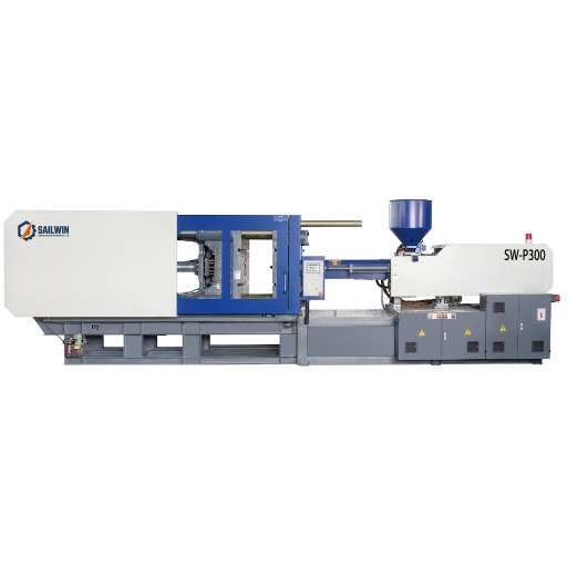
Industrial Machinery Assembly & Workshop: sw p300 pet preform injection molding machine
6. Layout Review Checklist
Use this list to test a layout before it is committed. Each item is a question with a factual answer, and a “no” is a cost you are choosing to accept.
Does any material cross its own path or share an aisle with finished goods? If yes, plan the flow again. Two aisles cost less than the permanent labour of a congested one.
Can each machine receive a mould with the crane or forklift available, without moving another machine? Fast changeover, mould handling and safe maintenance all depend on this.
Is every dryer within a short conveying distance of the machine it feeds? Long runs degrade dew point, add conveying load and multiply leak points.
Are the two air pressure bands separated, with receivers near the blowing machines? This is the single cheapest way to stabilise blowing pressure and to capture exhaust-recovery savings.
Is the preform store sized from the shift difference and changeover intervals, and does it enforce FIFO physically? A buffer that cannot be reached in the right order is not a buffer.
Can the plant identify which machine, cavities and hour produced a given preform lot? When a blowing problem appears, this determines whether it takes an hour or a week to find the cause.
Is there space for the machines you intend to buy next, including their services? Layout changes cost far less on paper than in a running plant. Sailwin machines ship in 30 to 45 days for standard configurations and 45 to 60 days for custom builds, are tested at full load before shipment and are commissioned on site in 3 to 7 days, with common wear parts dispatched within 48 hours and remote engineering support available 24/7 — which means the layout, not the machine delivery, is usually the longer lead item.
Frequently Asked Questions
Plan the Material Flow Before the Machine Positions
Send your bottle drawing, container sample or target output. Our engineering team replies with a machine recommendation, mould assessment and factory-direct quotation within 24 hours.
Related Reading:
• PET Preform Injection Molding Machines — SW-P Series
• Factory Layout for PET Blow Moulding Lines
• Site Installation of a Preform Injection Machine
• Resin Drying Before Preform Moulding
• Robot Take-Out and the EUROMAP 67 Interface
• Packing and Palletising at the End of the Line



