
Conveyors are the cheapest equipment on a bottling line and the most common cause of it not reaching its rated output. A filler is specified with a nameplate speed; the line runs at whatever the conveyor system allows. When bottles fall at a transfer, back up hard against a stop, or scuff because a guide rail is set 2 mm too tight, the filler spends part of every shift waiting for an empty bottle — and the loss never appears in the filler’s performance record.
The cost of getting conveyor design wrong arrives in three forms. Fallen bottles stop the machine and cost product. Excess accumulation pressure deforms lightweight PET, so filled bottles reach the lab thinner-walled than the preform that made them. Bad rail and transfer geometry scuffs decoration and creates jams that operators learn to live with, which is the worst outcome of all: a line that runs, but never at the speed it was bought for.
This is the part of a line where engineering input pays back fastest. Sailwin has built filling equipment for 15+ years, with 500+ machines delivered into 60+ countries, CE marking, ISO 9001:2015 manufacturing and a 2-year whole-machine warranty. Our 3-in-1 rinse-fill-cap monoblocs use 180° flip grippers for bottle rinsing, laminar flow filling valves, constant magnetic torque capping, and isobaric filling for carbonated products, in SUS304/316L construction with 24-hour factory acceptance testing and quick changeover. This article covers how to size conveyor speed and pitch, how accumulation pressure really behaves, and how to specify conveyors as part of the filling line rather than as an afterthought.
Key Takeaways
- Size conveyors from the filler’s rated output, then add margin. At typical line speeds the conveyor must be able to run faster than the filler and not slower, so it never becomes the constraint.
- Accumulation pressure is a quality variable, not just a jam risk. Backpressure is what deforms lightweight PET, so buffer length and zero-pressure control belong in the packing specification.
- Decide bottle handling before you order chain. Neck handling changes conveyor type, rail position, transfer design and the whole changeover procedure.
Send Your Line Layout for a Conveyor Review
Share bottle size, weight, filler output and line length — Sailwin engineers return conveyor speed, pitch mix, accumulation sizing and changeover time.
1. Conveyor Speed, Pitch and the Bottle-to-Bottle Relationship
Conveyor speed is not chosen freely. It follows from the filler’s rated output, the number of bottles the conveyor carries per metre, and the transients created by stoppages elsewhere on the line. The relationship that matters is simple: at a given output, the faster the conveyor runs, the sparser the bottles, and the less stable each one is. That is why lightweight bottles and high speeds pull in opposite directions, and why a line running thin-wall PET usually needs either a lower speed with more accumulation, or a different handling principle entirely.
Pitch is the second half of the equation. Bottle spacing on a table-top chain determines how many bottles are in contact at any moment, which in turn determines the pressure transmitted back through the queue. Running bottles tightly increases line density and throughput per metre of conveyor, but it also means more contact points, more scuffing, and a harder stop when a bottle jams at a transfer. Running them loosely reduces contact but makes single bottles easier to topple when a machine starts and stops.
The practical outcome is that conveyors are usually specified in more than one speed zone: a metering or single-filing section immediately before the filler running at line speed, and an accumulation section running slower so bottles can queue without building momentum. Designing one speed for the whole line is the most common conveyor mistake, and the symptom is a line that only behaves when it is new and clean.
| Design parameter | What it controls | Symptom when it is wrong |
|---|---|---|
| Conveyor speed | Bottle spacing and stability at each machine interface | Bottles topple on start-up; filler starves on restart |
| Pitch and line density | Number of simultaneous contact points | Scuffing and label damage on decorated bottles |
| Filing arrangement | Single-file metering versus multi-lane transport | Infeed fights the machine; timing screws wear early |
| Rail clearance | Bottle guidance without pinching | Scuff marks, oval distortion, rail wear |
| Accumulation length | Buffer time between machine stoppages | Short stops cascade; labeler stop empties the filler |
| Chain material and lubrication | Friction, hygiene and washdown compatibility | High backpressure, contamination risk, frequent cleaning stops |
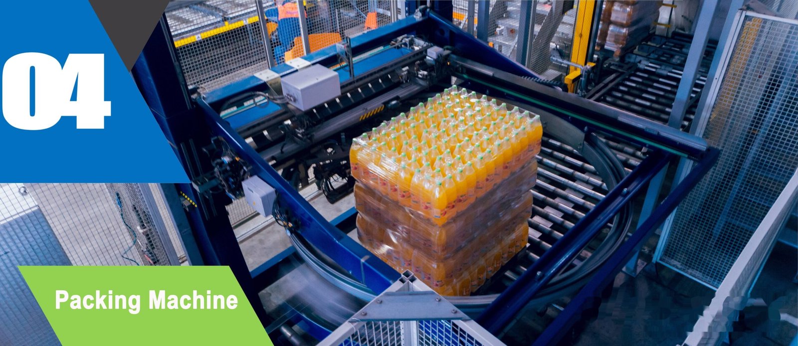
Precision Engineering & Core Components: turnkey bottling line step 04 shrink wrapping packing machine
2. Curves, Transfers and What Accumulation Pressure Does to Bottles
Every bottle on a conveyor that is touching the one in front of it is part of a chain of force. The force at the back of a full accumulation table is the sum of the friction of everything ahead of it, which is why a long queue of light bottles can still push hard enough to deform the bottle at the front. Zero-pressure accumulation matters for exactly this reason: it is a control strategy that keeps bottles separated in blocks rather than allowing them to compress into a single mass.
For thin-wall PET, this is a quality issue before it is a mechanical one. A bottle that is compressed in a queue does not spring back perfectly, especially while warm after hot filling or before the internal pressure of a carbonated product has stabilised. The result is an oval cross-section that shows up later as a labelling problem, a poor top-load result, or a case that will not pack cleanly. Engineers who size accumulation tables only for buffer time and ignore the pressure they generate usually find the consequences in a different department.
Curves and transfers are where the geometry fights the physics. Bottles like to travel in a straight line; every curve introduces a differential speed between the inside and outside of the bottle footprint, and every transfer introduces a gap the bottle has to cross. Typical design practice is to give curved sections a larger radius than they appear to need, to keep guide rails parallel through curves rather than following the chain centreline, and to make transfer plates as short as the bottle diameter allows. On lightweight bottles, an air conveyor that carries the bottle by its neck support avoids most of these problems entirely, because nothing is pushing on the body wall.
A conveyor that never jams is not necessarily a good conveyor. The engineering question is whether the bottles that passed through it are still the shape they were when they came out of the blow moulder.
3. Matching Conveyors to Filler, Capper and Rinser Interfaces
Conveyors do not exist on their own; they exist to deliver a bottle to a machine in a state the machine can accept. That means the infeed to a rotary filler needs a consistent single-file stream at a stable pitch, which is normally achieved with a timing screw rather than with rails alone. A screw that is worn or set for the wrong bottle diameter produces a stream that arrives fractionally early or late on every pocket, and the filler compensates by slowing down — an invisible loss that shows up as a line that never quite hits its rated speed.
Capping imposes its own requirement. Constant magnetic torque capping needs the bottle to be positively held while the cap is applied, otherwise the whole bottle rotates instead of the cap. Anti-rotation rails or a gripper belt at the capper is therefore a conveyor decision, not a capper decision. Where a monobloc performs rinsing, filling and capping in one machine, this is largely handled internally with grippers, which is one reason 3-in-1 designs are less sensitive to upstream conveyor quality than separate machines linked by transfer chain.
The rinser interface matters for a different reason. Where bottles are rinsed by 180° flip grippers inside the machine, the conveyor only has to deliver upright bottles to a defined pick-up point. Where rinsing happens off-machine, the conveyor has to survive water, and drainage and hygiene become the dominant design constraint rather than line efficiency. Specifying conveyors before this decision is made is how lines end up with wet, inadequately drained transfer sections that become a microbiological problem rather than a mechanical one.
4. Materials, Lubrication and Hygiene
Chain material decides friction, and friction decides how hard your bottles push each other. Steel table-top chain moves freely on soap-based lubrication, which is effective but introduces water, foam and slip risk into the filling hall. Plastic chain can run dry or with a light lubrication regime, which suits dry areas and reduces cleaning load, but has a lower allowable pull and needs more support. Neither choice is universally right; the decision follows the product, the hygiene regime and the bottle weight.
Where equipment is built in SUS304 or SUS316L for washdown — as Sailwin filling lines are — the conveyor and its supports should be specified to the same standard. A stainless machine fed by a painted steel conveyor frame is a corrosion site waiting to happen, and the failure appears at the frame rather than at the machine, which is why it is often diagnosed late. Drainage falls into the same category: water that cannot leave a transfer section will find a way into the bottle path.
| Area of the line | Conveyor priority | What to specify |
|---|---|---|
| Filler infeed | Pitch accuracy and repeatability | Timing screw, servo-driven metering, rigid single-file rails |
| Between machines | Buffer time without pressure build-up | Zero-pressure accumulation, block discharge, low-friction chain |
| Capper and labeller | Positive bottle location | Anti-rotation rails or gripper belt, stable support under the base |
| Washdown and rinsing areas | Hygiene, drainage and corrosion resistance | SUS304/316L frames, open drainage, no horizontal ledges |
| Case packing and palletising | Discharge synchronisation | Speed matching to the slowest machine downstream, not the filler |
5. Case Study: A Beverage Line That Would Not Hold Its Rated Speed
A beverage plant in Southeast Asia ran a filling line that reached its rated output only in the first hour of a shift, then lost speed steadily and blamed the filler.
- Rated speed achievable at start of shift, degrading as the line filled with bottles
- Occasional ovality and label damage traced to the accumulation section rather than to filling
- Conveyor sized for transport only: one speed, minimal buffering, rails set by eye
- Conveyor split into metering, transfer and accumulation zones with different speeds
- Zero-pressure accumulation introduced before the labeller; rail clearances set to bottle diameter
- Infeed timing screw matched to the filler pocket pitch; changeover procedure documented per format
- Line speed held through the shift instead of decaying as accumulation built up
- Ovality and label complaints diagnosed at the conveyor rather than after filling
- Format changeover treated as a conveyor task with defined rail positions and a written sequence
Scenario based on a Sailwin customer project; site-specific figures available on request during engineering review.
6. Specifying Conveyors With the Line, Not After It
The single most effective change a project team can make is to treat the conveyor system as part of the filling line specification rather than as civils and steelwork. That means the conveyor supplier and the filler supplier work from the same bottle drawing, the same rated output, and the same changeover time target. Sailwin builds filling lines with quick changeover as a design requirement and tests them at full load for 24 hours before shipment, which is the point at which conveyor and machine interfaces show their real behaviour.
- Start from the slowest machine, not the filler. Conveyor speed and buffer size should be driven by the machine that constrains the line, which is often the labeller or the case packer.
- Specify accumulation in seconds, not metres. Buffer length is only meaningful when converted into how long the line can survive a downstream stop.
- Test with the lightest and hardest bottle in the portfolio. A conveyor tuned on a heavy glass bottle will behave differently on thin-wall PET at the same speed.
- Document rail positions per format. Precise changeover depends on repeatability, so rail settings belong in a changeover record, not in an operator’s memory.
- Plan the FAT with bottles in the line. Running a line dry proves the motors work; it does not prove the transfers do.
Finally, connect the conveyor to the line controls. Speed changes, accumulation block release and jam detection should be driven by the PLC rather than by independent inverters, so that a stop anywhere on the line produces a predictable response everywhere else. Because Sailwin machines monitor 40+ parameters through the PLC in real time, a conveyor system that reports into the same layer makes it possible to distinguish a filling problem from a transport problem using one dataset — which is the difference between fixing a line and arguing about it.
Specify Your Conveyor System With the Line
Send bottle drawings, rated output and format list — Sailwin engineers return speed zones, accumulation sizing, rail positions and a changeover sequence.
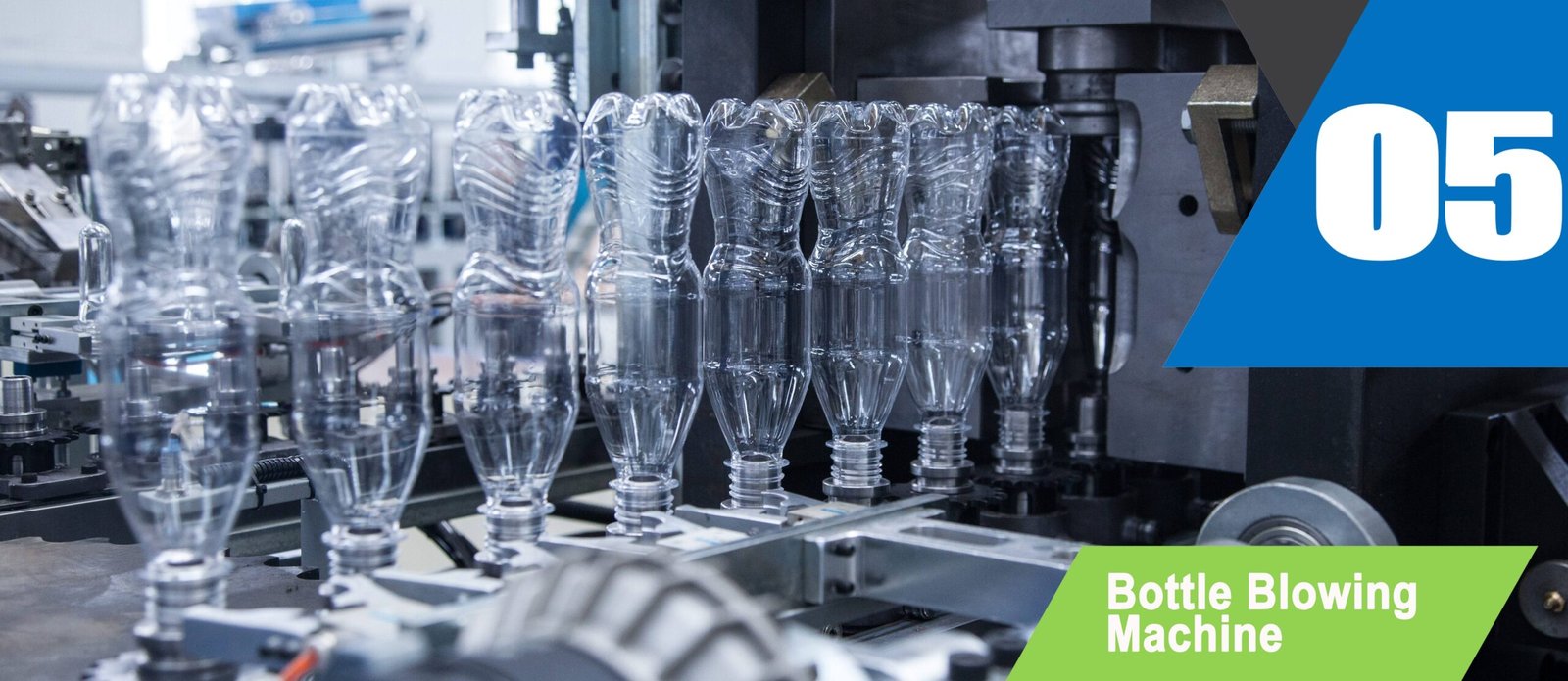
Industrial Machinery Assembly & Workshop: turnkey bottling line step 05 automatic bottle blowing machine
7. Frequently Asked Questions
Make the Conveyor Part of the Line Specification
Send your bottle drawing, container sample or target output. Our engineering team replies with a machine recommendation, mould assessment and factory-direct quotation within 24 hours.
Related Reading:
• Filling Machines: Monobloc, Isobaric, Hot Fill and 5-Gallon Lines
• Filling Line Layout Design
• 3-in-1 Monobloc Rinse-Fill-Cap Machines
• Capping Torque Control on Filling Lines
• Filling Machine Changeover Procedure
• Bottle Rinsing: Methods and Machine Integration



